Page 1 of 2
PIC18F57Q84 UART Error
Posted: Mon Aug 10, 2026 9:29 am
by seokgi
Hello.
I am trying to proceed with a project using the PIC18F57Q84. I had trouble because it wouldn't compile. After receiving advice on how to switch compilers, it now compiles successfully. However, UART communication is not working. When I checked with an oscilloscope, the waveform phase was reversed in the output.
Please tell me how to fix this.
Thank you.
Re: PIC18F57Q84 UART Error
Posted: Mon Aug 10, 2026 9:58 am
by LeighM
Could you provide a sample picture and what data it represents that you are sending
Re: PIC18F57Q84 UART Error
Posted: Tue Aug 11, 2026 1:36 am
by seokgi
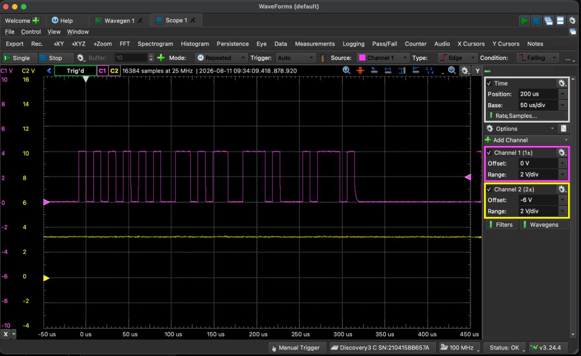
The pink waveform is the waveform outputting "Test" from the PIC18F57Q84.
- PIC18F57Q84_Wave_Test.jpg (118.28 KiB) Viewed 3304 times
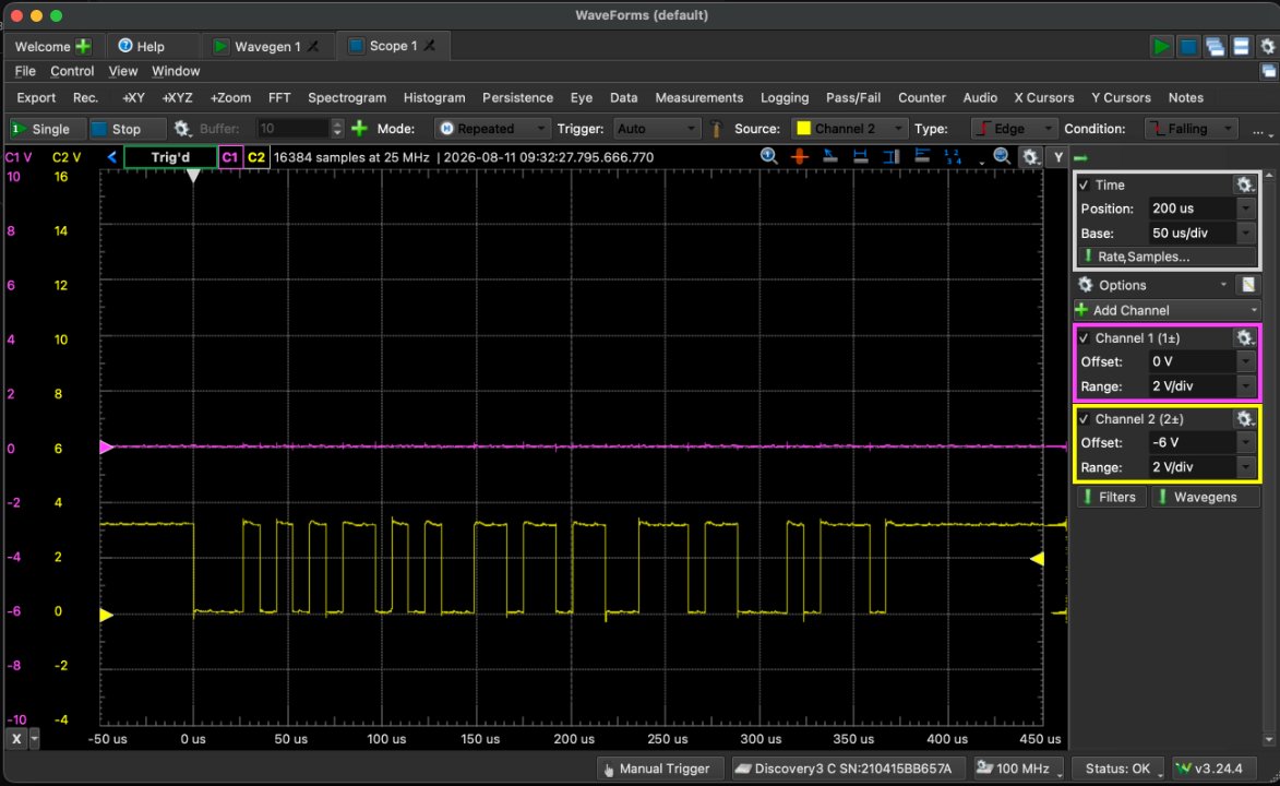
The second yellow waveform is the waveform outputting "Test" from another device (PC USB-Serial).
- USB_Wave_Test.jpg (118.92 KiB) Viewed 3303 times
Re: PIC18F57Q84 UART Error
Posted: Tue Aug 11, 2026 1:31 pm
by LeighM
Looks like the TX output is being forced into a non-Idle (break) state
One for Ben and the UART CAL I think
(UxCON1 issue with this device?)
Re: PIC18F57Q84 UART Error
Posted: Wed Aug 12, 2026 10:27 am
by BenR
Hmm that's pretty odd indeed.
There is a register that controls the state of the TX pin but it completely flips the signal and the signal looks mostly ok, though not 100% correct.
Our CAL doesn't write to the register in question and the default state should be 0 so again this is very odd.
You could try with a C icon changing the 1 for the specific UART channel you're using.
Let us know if this makes a difference.
Re: PIC18F57Q84 UART Error
Posted: Wed Aug 12, 2026 11:00 am
by LeighM
Hi Ben.
The signal looks inverted, but if you analyse the data it looks correct for "Test"
So I think it is in break mode in the inter data gaps.
There is a bit in UxCON1 that controls break, I wondered if that is causing it, perhaps it is getting inadvertently set?
Re: PIC18F57Q84 UART Error
Posted: Wed Aug 12, 2026 11:57 am
by BenR
Thanks Leigh,
We can also try this using this C code to see if this makes a difference.
The CAL code does write to this register on initialise but the reset value should be 0x00 and we just set the ON bit which should be bit 7.
Could be a silicone bug, in fact I'll check the errata document for the chip now.
From the Errata :-
UART TXDE Signal May Go Low before the STOP Bit Has Been Entirely Transmitted
The UART Transmit Drive Enable (TXDE) signal could potentially transition into a low state before the UART STOP bit has been entirely transmitted due to the effects of parasitic capacitance on the TX line. In some applications, this could result in communication being prematurely terminated due to the TXDE bit going low before the STOP bit has had enough time to settle.
Work around To ensure that the STOP bit settles into its final logic state before the TXDE signal transitions low, a biasing circuit can be implemented. A biasing circuit allows the TX line to either be driven high or low, rather than being left in a floating tri-state mode where prolonged rise or fall times could lead to communication being disrupted. This bias circuit should only be implemented on one end of the serial bus, and a termination resistor should be used on the other end.
So I think they are recommending an external pull up resistor on the TX pin, maybe 10K - 100K?
Re: PIC18F57Q84 UART Error
Posted: Wed Aug 12, 2026 12:48 pm
by LeighM
Good research, that sure looks like the issue then
Re: PIC18F57Q84 UART Error
Posted: Thu Aug 13, 2026 6:09 am
by seokgi
This seems to be about RS-485 terminator resistors.
Of course, I tried attaching 4.7K Ohm and 10K Ohm pull-up resistors, but the result is a communication failure.
Re: PIC18F57Q84 UART Error
Posted: Thu Aug 13, 2026 7:17 am
by seokgi
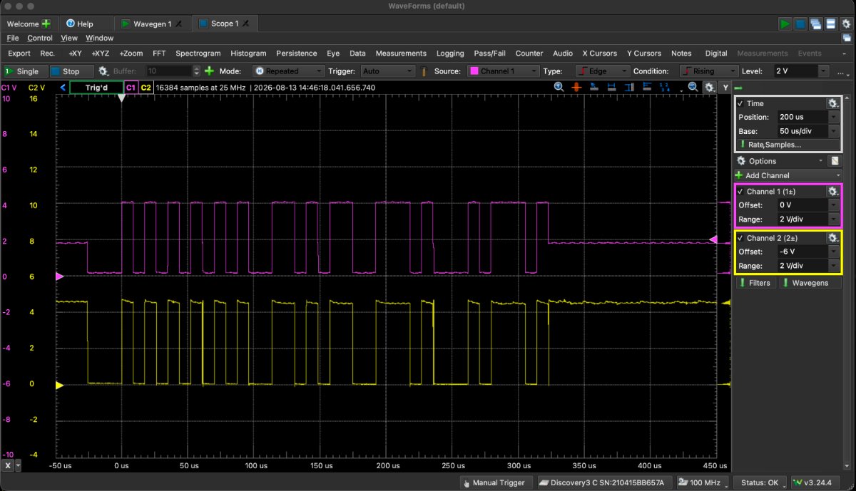
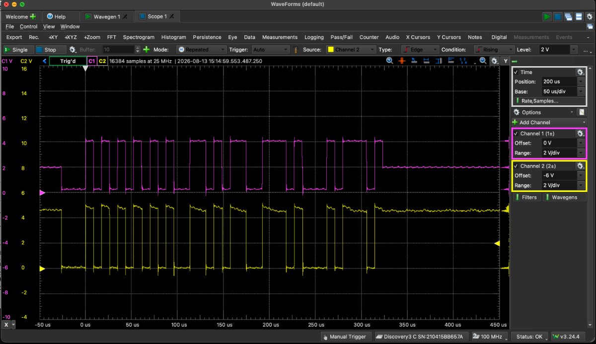
Communication works if the pull-up resistor is changed to 3 kiloohms. It is expected that this result is due to the threshold level. It appears that a pull-up resistor of about 2k ohms is necessary for stable communication.
The pink color is the waveform directly connected to the MCU, and the yellow color is the isolated waveform passed through the TLP2355.
Waveform-3K Ohm Pullup
- Waveform-3K.jpg (118.39 KiB) Viewed 3170 times
Waveform-2K Ohm Pullup
- Waveform-2K.jpg (123.98 KiB) Viewed 3170 times