Hello,
I'm triing to make nrf24l01 transciever and reciever. Interesting this is that everything worked, but it stoped, and I cant make it to work again.
Can somebody take a look at the programs.
Predajnik is TX
Prijemnik is RX
THX
nrf24L01
Moderator: Benj
nrf24L01
- Attachments
-
- NRF24L01_Predajnik.fcfx
- (10.89 KiB) Downloaded 268 times
-
- NRF24L01 Prijemnik.fcfx
- (10.88 KiB) Downloaded 279 times
-
electron67
- Posts: 323
- Joined: Sat Jan 12, 2008 2:08 am
- Has thanked: 106 times
- Been thanked: 48 times
Re: nrf24L01
Hello
I also did the same thing, I did my own TX and RX and excellent work with the example published in Wiki, I work as 3 continuous transmissions, after that I could no longer run the nRF24L01. . .
Enrique
I also did the same thing, I did my own TX and RX and excellent work with the example published in Wiki, I work as 3 continuous transmissions, after that I could no longer run the nRF24L01. . .
Enrique
-
Benj

- Matrix Staff
- Posts: 15312
- Joined: Mon Oct 16, 2006 10:48 am
- Location: Matrix TS Ltd
- Has thanked: 4803 times
- Been thanked: 4314 times
- Contact:
Re: nrf24L01
Hello,
I wrote the component based on an Arduino library to the point where it was working nicely. I haven't seen the suddenly no longer working problem and it was certainly up and running for a fair bit longer than 15 minutes.
Could it be something to do with voltages? Is the module powered at 3V3? if so then what voltage is your microcontroller I/O running at? If it's running at 5V then it could be that which is damaging the module over time.
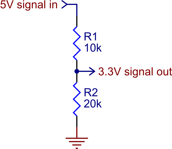
A simple way to shift your 5V outputs to 3V3 is to use potential dividers on each output pin (CE, CSN, MOSI, CLK). MISO is an input pin so potential divider is not needed for this one.
https://a.pololu-files.com/picture/0J14 ... e8ec7aa643
I wrote the component based on an Arduino library to the point where it was working nicely. I haven't seen the suddenly no longer working problem and it was certainly up and running for a fair bit longer than 15 minutes.
Could it be something to do with voltages? Is the module powered at 3V3? if so then what voltage is your microcontroller I/O running at? If it's running at 5V then it could be that which is damaging the module over time.
A simple way to shift your 5V outputs to 3V3 is to use potential dividers on each output pin (CE, CSN, MOSI, CLK). MISO is an input pin so potential divider is not needed for this one.
https://a.pololu-files.com/picture/0J14 ... e8ec7aa643
Regards Ben Rowland - MatrixTSL
Flowcode Product Page - Flowcode Help Wiki - Flowcode Examples - Flowcode Blog - Flowcode Course - My YouTube Channel
Flowcode Product Page - Flowcode Help Wiki - Flowcode Examples - Flowcode Blog - Flowcode Course - My YouTube Channel