Page 3 of 3
Re: Using FFT_test.fcfx
Posted: Mon Jun 15, 2015 4:30 pm
by SHORTCIRCUIT
Hi Ben
Thanks for the tip on the Level detector, something new to play with.
Larry
Re: Using FFT_test.fcfx
Posted: Mon Jun 15, 2015 5:00 pm
by Benj
Whoops found a little bug in my example, this is now working very well.
Re: Using FFT_test.fcfx
Posted: Mon Jun 15, 2015 11:01 pm
by SHORTCIRCUIT
Hi Ben
In your example DSPFFT3, what causes trigger variable to change to 1? Is it that the tick_all_buffers has caused the buffers to reach the end of the buffer file. I searched and could not find any reference to this. I have seen you use trigger before but did not understand what was happening.
I also noticed that your interrupt is set for twice the sample rate, for instance, for 8000 sample rate your interrupt is set for 16,000hz. Please explain.
Larry
Its now later in the day and I discovered that trigger is returning 1 after collecting 65 pieces of buffer data and the buffer size is 128. I don't understand. I discovered this by putting a counter in the timer-tick macro.
Re: Using FFT_test.fcfx
Posted: Tue Jun 16, 2015 10:04 am
by Benj
Hi Larry,
The tick all buffers will move each of the circular buffer indexes along to the next location in the buffer.
If we reach the end of one of the buffers and wrap around back to the start then the trigger variable will be set.
The 8KHz label is a mistake, I must have upped the sample rate to 16KHz without noticing to change the comment.
Its now later in the day and I discovered that trigger is returning 1 after collecting 65 pieces of buffer data and the buffer size is 128. I don't understand. I discovered this by putting a counter in the timer-tick macro.
The FFT macro will move the buffer locations to perform the FFT calculations. At the end of the FFT process I reset all the buffer indexes to 0 before restarting the timer, however it looks like I have failed to do this for the additional buffer I added so maybe this is why it is triggering too early for you.
Re: Using FFT_test.fcfx
Posted: Tue Jun 16, 2015 2:08 pm
by SHORTCIRCUIT
Hi Ben
Thank you for the responses.I have learned a heck of a lot from your responses.
In your post above, I was not concerned about the comment as I know it doesn't do anything. I am interested that the interrupt freq is twice that of the 8000hz entered under the calculation tab of the FFT properties. Is it ok for it to be different then the interrupt freq? If yes, does it need to be a multiple of the sample rate calculation.
I added in the set index to 0 on the 4th buffer and trigger now happens at the correct count of 128.
Larry
Re: Using FFT_test.fcfx
Posted: Tue Jun 16, 2015 2:51 pm
by Benj
Hi Larry,
Thank you for the responses.I have learned a heck of a lot from your responses.
No problem, glad to be of help.
I am interested that the interrupt freq is twice that of the 8000hz entered under the calculation tab of the FFT properties
The calculation properties as part of the DSP components are purely cosmetic. They allow you to get an idea of what is going on in terms of things like nyquist, freq bin count and freq range per bin but do not actually change the underlying code. I think there are a couple more DSP components with similar helpful calculations.
I added in the set index to 0 on the 4th buffer and trigger now happens at the correct count of 128.
That's brilliant thanks for letting me know.

Maybe the DSP FFT should reset all buffer indexes automatically after being called? I will think on this just in case there are any potential consequences.
Re: Using FFT_test.fcfx
Posted: Thu Nov 05, 2020 4:01 pm
by AbhijitR
Hello! Ben
good evening
Benj wrote: ↑Mon Jun 15, 2015 4:03 pm
Aha yes that might explain things. The ADC input has to be positive, negative voltages will just be read by the micro as 0's.
Kindly excuse to repeat, your post clearly mention, but absolutely no chance to recognize the negative voltage?
Because in my hardware once i disconnect the sensor probe i receive negative voltage (-0.5V) on the ADC pin, once i connect the sensor probe the reading is 0V, this is correct, but what if i want to detect the sensor probe is open, any trick.
Thank you.
Abhi
Re: Using FFT_test.fcfx
Posted: Thu Nov 05, 2020 10:47 pm
by medelec35
Hi Abhi,
Any voltages less the minimum resolution E.g for 10 bit = 5/1024 = 4.88mv will be treated a 0
That will include negative voltages.
You will need to be careful with negative voltages as the clamping diodes will clamp the ADC pin to -0.7v
If current is not limited and voltage is lower than -0.7v then the microcontroller will be damaged.
What about trying this circuit?:
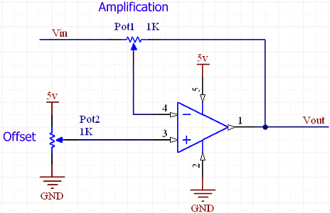
- DC Level shifter.png (44.95 KiB) Viewed 10194 times
From
here
Re: Using FFT_test.fcfx
Posted: Thu Nov 05, 2020 11:09 pm
by Bachman
Hello!
No, there is no option to measure negative voltage via simple microcontrollers, without extra analogue components.
You can get negative results, if the controller have special ADC. Eg. PIC18FxxK80 family have differential ADC. The ADC module (optionally) have two inputs, positive and negative. If the voltage on the negative input is higher than the voltage on the positive input, the ADC will give you negative results, but both inputs're positive. Lots of external ADC chips have differential inputs, eg. ADS1115, MCP3550.
The input voltages must be within the limits, see the IC-s datasheet. This limit on the ...K80 family is -0.3 to 7.5 V,
respect to VSS. If you want to measure negative voltage, you have to mirror it to the positive area, eg. with an inverting operational amplifier. The trap, if the opamp get positive input, the output will be negative. One solution is if you're using precision rectifier. In this case, both negative and positive input will give you positive output. Other solution is to measure negative and positive voltages is to add offset voltage to the voltage what you want to measure.
I don't know every microcontrollers, maybe some of them are can handle negative voltages but i'm not sure about this.
Edit: medelec35 was faster.

Re: Using FFT_test.fcfx
Posted: Fri Nov 06, 2020 7:09 am
by AbhijitR
Hello! Martin
Many thanks for the explanation about the minimum resolution, to be honest i was not aware of that, something new to learn, i will check the link you provided.
Hello! Bachman
Thanks to you and Martin too for the suggestion about using the analog ckt, actually the present Op-Amp gadget what i am using works well when the loop is closed, i wanted to trip the output once the loop gets open, i think i will give a try with the chips you suggested, for the moment i am using PIC18F26K22.
Thank you again to both of you.
Abhi