Page 1 of 2
RTC for MIAC(Part two)
Posted: Tue Nov 06, 2012 11:16 pm
by Enamul
Hi Stuart
In this thread, we will start with basic MIAC program to make familiarization with MIAC. After couple of basic program, we will move to CAN test using MIAC and slave module without changing the slave circuitry. We will keep slave end of CAN bus as it is. Only MASTER end of CAN bus will be connected to MIAC (L) and (H) terminal and this time we will remove 120 ohm from Master end CAN bus and in MIAC we will close TA and TB terminal which will ultimately connect terminating resistor inside MIAC.
Have you tested any program in MIAC or it's still virgin? If so, I can post simple program to test MIAC.
Re: RTC for MIAC(Part two)
Posted: Tue Nov 06, 2012 11:23 pm
by acestu
Hi Enamul,
I have powered up the MIAC and had a look at the test program.
thanks
Acestu
Re: RTC for MIAC(Part two)
Posted: Tue Nov 06, 2012 11:45 pm
by Enamul
Hi Stuart,
I think the Keypad test is a nice program for MIAC to start with. This will help you to test LCD and Keypad components of MIAC which will be useful in our purpose later on..
Re: RTC for MIAC(Part two)
Posted: Fri Nov 09, 2012 9:27 am
by acestu
Hi Enamul,
I have installed the drivers for the MIAC and programmed your test program successfully
Thanks
Acestu
Re: RTC for MIAC(Part two)
Posted: Fri Nov 09, 2012 3:06 pm
by Enamul
That's nice. Here is another test code for ADC testing in MIAC..Here are 4 channels but you can use 1,2 or even 4.
Re: RTC for MIAC(Part two)
Posted: Sun Nov 11, 2012 6:01 pm
by acestu
Hi Enamul,
I have programmed the MIAC with the Voltmeter code successfully but I don't know what I am supposed to do with it, I would imagine that it tells you the voltage at certain pins of the MIAC , I cannot see any marked I1, I2, I3 and I4.
Thanks
Acestu
Re: RTC for MIAC(Part two)
Posted: Sun Nov 11, 2012 6:31 pm
by Enamul
Hi Stuart
You should be able to see I1, I2, I3, I4 in MIAC as can be shown here..
- MIAC.png
- (464.42 KiB) Downloaded 12260 times
You can see right to OR terminal I1, I2, I3 & I4 terminals. If you put variable voltage in those pin you should be able to see voltage in display.
Re: RTC for MIAC(Part two)
Posted: Sun Nov 11, 2012 6:42 pm
by acestu
Thanks Enamul
Do I use the 0v for ground / negative ? , I don't want to damage anything !
Thanks
Acestu
Re: RTC for MIAC(Part two)
Posted: Sun Nov 11, 2012 10:01 pm
by Enamul
Hi
0V is GND obviously but which -Ve you mean?
Re: RTC for MIAC(Part two)
Posted: Sun Nov 11, 2012 10:23 pm
by acestu
Yes Sorry
thanks
Acestu
Re: RTC for MIAC(Part two)
Posted: Sun Nov 11, 2012 10:26 pm
by Enamul
No problem at all.
Re: RTC for MIAC(Part two)
Posted: Sun Nov 11, 2012 10:47 pm
by acestu
Hi Enamul,
I have shorted out the TA & TB terminals on the miac and connected the can bus high and low then removed the resister from the master end....
thanks
Acestu
Re: RTC for MIAC(Part two)
Posted: Sun Nov 11, 2012 10:57 pm
by Enamul
That's great. Here is the RTC code for MIAC and slave..
Re: RTC for MIAC(Part two)
Posted: Sun Nov 11, 2012 11:19 pm
by acestu
Hi Enamul
I have programmed the MIAC and the Slave and when I power them both up the slave is showing time but the miac has a blank screen ?
Should the MIAC display show anything if the Canbus is not receiving anything ?
thanks
Acestu
Re: RTC for MIAC(Part two)
Posted: Mon Nov 12, 2012 2:20 pm
by Enamul
Sorry there was a problem in MIAC code..it should be OK now.
Re: RTC for MIAC(Part two)
Posted: Mon Nov 12, 2012 7:55 pm
by acestu
Hi Enamul,
I have reprogrammed the Miac but I still only get the "MIAC RTC Unit" text on the screen, I have a wired link in the TA and TB sockets and just 1 resister on the slave end of the Can Bus, but it is a 100 ohm, should I try and find a 120 ohm resister ?
thanks
Acestu
Re: RTC for MIAC(Part two)
Posted: Mon Nov 12, 2012 8:11 pm
by Enamul
You can try but I don't think that is so critical. May be something wrong in the internal CAN and external CAN of MIAC. We have to go through some other tests may be.
Re: RTC for MIAC(Part two)
Posted: Mon Nov 12, 2012 8:27 pm
by acestu
Ok, that's great Enamul, only my luck hey ........
Thanks
Acestu
Re: RTC for MIAC(Part two)
Posted: Wed Nov 14, 2012 1:01 am
by acestu
Hi Enamul,
I have connected the slave board back up to the old master breadboard and the unit is working with both LCD modules showing the time and date, therefore the problem must be between the Canbus and the MIAC, I now have 120 ohm resistors on the Canbus as well, if you know of a test for the MIAC canbus I would be grateful.
thanks
Acestu
P.S. can both units be hooked up to the Canbus at the same time ?
Re: RTC for MIAC(Part two)
Posted: Wed Nov 14, 2012 2:36 am
by acestu
I have been looking through the MIAC manual and it says that I require 4 wires as per my enclosed diagram, on my setup I have a link in the TA & TB connections, the Can bus Hi & Low in the L & H connections then I have a link in the M & +v connections, but I have nothing in the 0v connection, is this right ?
Thanks
Acestu
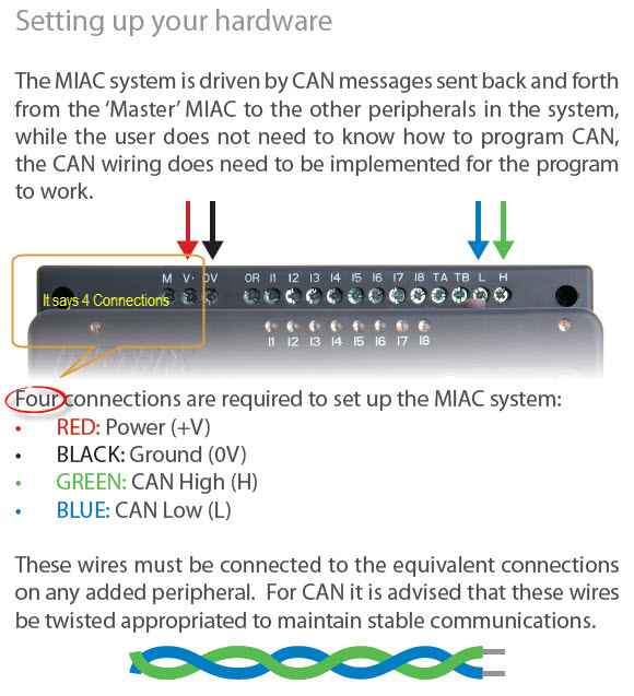
- miac_wires.jpg (92.56 KiB) Viewed 21192 times
Re: RTC for MIAC(Part two)
Posted: Wed Nov 14, 2012 7:03 am
by Enamul
then I have a link in the M & +v connections, but I have nothing in the 0v connection, is this right ?
I haven't told you anything about M& +V link. We don't need M pin at all. +V can be used or you can leave it depending on you. +V can be used as power supply for slave. MIAC datasheet is showing that..but you can use separate power supply for slave if you have or you can use +V. But
you have to connect 0V pin of MIAC to GND of slave to have common ground. So for our case we can use 3 or 4 not necessary it must be 4.
Re: RTC for MIAC(Part two)
Posted: Wed Nov 14, 2012 9:58 am
by acestu
Hi Enamul,
Can I just clarify what is meant by "So for our case we can use 3 or 4 not necessary it must be 4." please, if you mean it must be 4 wires, could you please show me how to connect to my breadboard
thanks
Acestu
Re: RTC for MIAC(Part two)
Posted: Wed Nov 14, 2012 10:54 am
by Enamul
Sorry for confusing you again. Can you please tell me where you running your slave PIC and RTC module from..I mean where it gets power from? If it's getting it's power from MIAC +V terminal in that case you will need 4 connections to slave. 2 are L& H, 1 is common GND (0V) and other is +V for slave +ve supply.
But if you are using separate power supply for Slave and RTC module you don't need +V connection of MIAC. You can simply ignore that. You need only L, H and 0V.
Re: RTC for MIAC(Part two)
Posted: Wed Nov 14, 2012 11:36 am
by acestu
Hi Enamul,
My Slave on the breadboard has its own +5v power supply that plugs into mains, and I am powering the MIAC from a mains PSU, so I think from what you are saying is
I only need to connect the Can Bus H & L , and connect the 0v on the MIAC to the neg rail on my breadboard
thanks
Acestu
Re: RTC for MIAC(Part two)
Posted: Wed Nov 14, 2012 12:01 pm
by Enamul
I only need to connect the Can Bus H & L , and connect the 0v on the MIAC to the neg rail on my breadboard
Absolutely right.