Page 1 of 1
Component Required
Posted: Mon Aug 14, 2017 12:39 pm
by Docara
Hi Ben
If possible would you be able to sort out a component for me (or tell me how to do it).
I require a push button switch which when pressed gives out a fixed analogue value, the value of which can be user altered in properties?
As you are no doubt aware some interface boards use a resistor ladder network connecting multiple switches to one analogue Pin.
Thank you
Matt
Re: Component Required
Posted: Mon Aug 14, 2017 2:41 pm
by electronix
Hi Docara.
Sounds like you need a pwm output and an RC filter(a resistor in series and a capacitor in parallel) after it, and by varying the dutycycle you will have an analog outputsignal.
About the values of the filter, it depends of how fast you need to alter the outputsignal.
regards
Nick
Re: Component Required
Posted: Mon Aug 14, 2017 3:06 pm
by LeighM
Hi Matt
Try the attached.
Leigh
Re: Component Required
Posted: Mon Aug 14, 2017 3:54 pm
by Docara
HI Leigh,
Thanks for the files. the way you have managed to bring simulated values into FC is something new to me.
Its not quite what I was after - perhaps a picture speaks a thousand words. I have purchased one of the following modules
https://www.maplin.co.uk/p/16x2-lcd-shi ... uino-n07dh
You will notice that located in the bottom left corner are 5 buttons connected to AN0. In my case theses values are (bytes) No Press = 249, RIGHT=4, UP=40, DOWN=86, LEFT=128 and SELECT =182
So what I was after is not a turning knob but a digital Push Button but giving out an equivalent analogue value to AN0. So when I pressed it on screen 86, say, would be delivered to the analogue routine.
Matt
Re: Component Required
Posted: Mon Aug 14, 2017 5:20 pm
by Benj
Hi Matt,
How about this? Should hopefully work in simulation and on the real hardware. You will have to tweak the values in the Ev_Timer macro a bit to give you the values you mentioned but should be enough for you to work with.
For example 249 would be (1 / 255) * 249 = 0.9764
Re: Component Required
Posted: Mon Aug 14, 2017 6:27 pm
by Docara
HI Ben
Thanks for the files, I have no problem reading the AN pin and/or assigning values I was just asking if it was possible to have a component which combined the operation and look of the existing Switch(Push,pcb) but give a fixed analogue value
I am unable to have 5 Pots on screen to simulate the five buttons because they all turn together, hence my request for assistance
Matt
Re: Component Required
Posted: Tue Aug 15, 2017 10:43 am
by medelec35
Hi Matt,
I have modified Flowchart Ben Posted.
I have not created a component as not had time.
I hope Flowchart works for you.
Martin
Re: Component Required
Posted: Tue Aug 15, 2017 11:46 am
by Docara
HI Kersing
Thank you for the file but I'm afraid its not what I am looking for.
I know how to read an ADC value I just want a fixed value when a button is pressed.
I have included the schematic so you can see where I'm coming from - look at the five switches all connected to AN0 via a resistor ladder network. These are the switches I want to replicate in FC
Thanks
Matt
Re: Component Required
Posted: Tue Aug 15, 2017 11:58 am
by medelec35
Hi Matt,
Docara wrote:I just want a fixed value when a button is pressed.
That is exactly what the flowchart does.
It does not Read ADC.
in fact the ADC component has been completely removed from the flowchart!
You press the left button and 128 appears on LCD etc s that is just assigned to an existing variable called
.
You can rename the
variable to whatever you like.
Have you ran a simulation and pressed each button, observing what's displayed on LCD?
Martin
Re: Component Required
Posted: Tue Aug 15, 2017 12:12 pm
by Docara
Medelec,
I am SO sorry I did you a disservice - no I didn't run the code .
I don't use the 3D Panel I took a quick look at the code saw nothing in the 2d panel and didn't see the LCD component on the chart I thought it was just reading the ADC port - (I think I need to apologise to Ben and Possible Leigh for the same reason) I was expecting to see a button (1) which I would use to build the five not a fully configures 'system'
Initial impressions are that it works like a charm I can't thank you enough.
Let me have a play and I'll get back to you
Thank you
Matt
Re: Component Required
Posted: Tue Aug 15, 2017 12:26 pm
by Docara
To Ben and Leigh
Further to my recent PM to you both and for the reasons posted above, I'm sorry I didn't give the work you did for me fair consideration.
I wanted to publically acknowledge that I was wrong implying you guys didn't produce what I asked for - you did.
Matt
Re: Component Required
Posted: Wed Aug 16, 2017 1:00 am
by chrisbooth1957

- kb1.JPG (111.99 KiB) Viewed 12436 times
- keyboard2.JPG (156.39 KiB) Viewed 12436 times
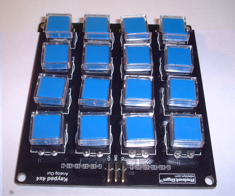
i have used the lcd sheild just reading a single analogue value and then lots of decisions but i agree a component would be good as you can get nice keyboards that only use a single pin of you microcontroller and have up to 16 buttons
Re: Component Required
Posted: Wed Aug 16, 2017 1:11 am
by chrisbooth1957
this may help you it is only an idea at the moment as there are some serious issues with the dmx recive , it uses an uno and lcd sheild the buttons alow you to set the dmx address and save it , it should work as it is if you want to play with something
Re: Component Required
Posted: Wed Aug 16, 2017 9:12 am
by Docara
Hi Medelec,
How are you passing the values of the switches into the ADC variable, I cant see anything in properties etc
thanks
Matt
Re: Component Required
Posted: Wed Aug 16, 2017 2:02 pm
by medelec35
Hi Matt,
If you look at Ev_Timer macro, you can see that a value has been assigned to a decision branch for each switch:
Martin
Re: Component Required
Posted: Wed Aug 16, 2017 3:50 pm
by Docara
Hi Martin,
I'll be damned!!!!!
Does this get added to the compiled or is it just simulation?
Oh by the way the routine works like a charm thank you again
Matt
Re: Component Required
Posted: Wed Aug 16, 2017 4:00 pm
by chrisbooth1957
you will be better looking at the higer swicth value first and use the > rather than = to allow for tolerences in the components ,, is if the vales shoud be 128 then 100 use > 114 as it is in between the 2 values , dont forget the board is probably built using 5% resistors giveing a max error of 10% as one could be 5% high and the other 5% low
Re: Component Required
Posted: Wed Aug 16, 2017 10:51 pm
by medelec35
Docara wrote:Does this get added to the compiled or is it just simulation?
Its simulation only, so you can do the normal ADC reading.
If you want to create your flowchart, I can amend it to work with both hardware and simulation.
Docara wrote:Oh by the way the routine works like a charm thank you again
Pleasure, glad it works.
Martin