Page 1 of 1
CAL_ADC component
Posted: Thu Dec 12, 2019 10:02 am
by fotios
Hi everyone
- Capture-1.jpg (80.49 KiB) Viewed 10085 times
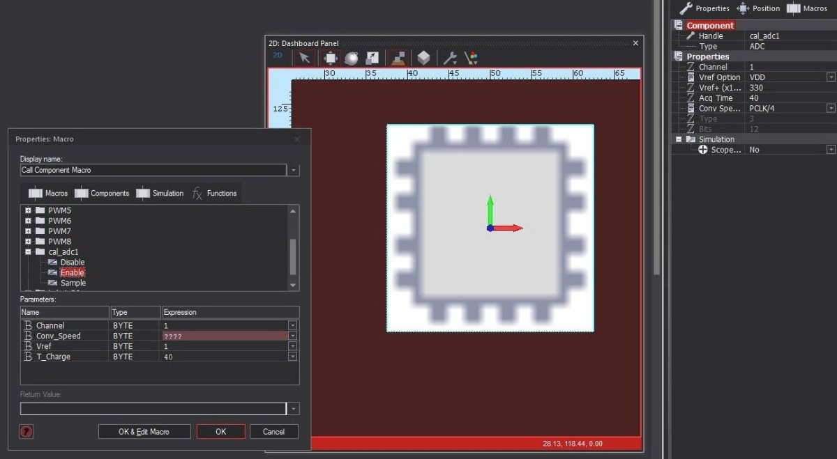
I like to use the CAL_ADC component from the TOOLS menu.
However, I can't understand what value I should give to the Conv_Speed byte.
You could see that in the properties panel I've selected as Conv_Speed = PCLK/4 (24MHz/4 = 6MHz).
Should I give the value 4?
Thanks
Re: CAL_ADC component
Posted: Thu Dec 12, 2019 11:52 am
by stefan.erni
Hi Fotios
I think you can just try it and if you don't need a highspeed, try it much slower (divide by 128) for ~ 180kHz
regards
Stefan
Re: CAL_ADC component
Posted: Thu Dec 12, 2019 1:16 pm
by fotios
Hi Stefan
Thanks for the reply.
Do you mean that I should write 128 in the Conv_Speed box?
I.e. if I write 255 I will get a 24000000/255=94117.6KHz conversion speed?
BTW I try to catch the peak voltage of a 1KHz square pulse, but with a variable duty cycle of 5 to 90%. That means that the lower speed to meet the Nyquist criterion is 2KHz.
Thanks
Re: CAL_ADC component
Posted: Thu Dec 12, 2019 3:53 pm
by stefan.erni
Hi Fotios
Ok. It depends on your processor. You can not choose that much for every processor. Choose only what appears in the selection box. Which processor do you use?
I try to catch the peak voltage of a 1KHz square pulse
That's not a big problem if it's square but if you like to measure the rectangle puls of 5% you need a much higher sampling rate.
Conv_Speed and samplingrate is not exactly the same.
Try to get the ad-converter working and running with your hardware. Let me know how it works
regards
Stefan
Re: CAL_ADC component
Posted: Thu Dec 12, 2019 7:12 pm
by fotios
Hi Stefan
My target is an STM32F3
Thanks
Re: CAL_ADC component
Posted: Fri Dec 13, 2019 12:38 pm
by LeighM
You could see that in the properties panel I've selected as Conv_Speed = PCLK/4 (24MHz/4 = 6MHz).
Should I give the value 4?
Yes (the value is the ADC clock divider 1, 2 or 4)
T_Charge is the number of clock cycles for the sample time
Values can be 1,2,4,7,19,61,181,601 (Flowcode selects the nearest value if you enter any other value)
Vref is not used by the Enable macro
Hope that helps,
Leigh
Re: CAL_ADC component
Posted: Fri Dec 13, 2019 1:48 pm
by fotios
Hi Leigh,
It helps a lot.
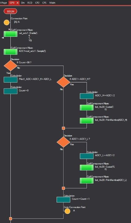
Now I try the ADC conversion to be based on a timer interrupt as you told me.
So when Timer 7 overflows, it calls the macro CP3 of which the first command is the "ADC_CAL Enable".
- Capture-1.jpg (33.03 KiB) Viewed 10020 times
I try various rollover values of timer 7, as well as various configurations of ADC_CAL and values of averaging (variable "Count") having in mind the Nyquist criterion, to get trustable readings of the peak voltage of square pulse.
For a duty cycle, greater than 25% is easy.
For less than 25% it is difficult as I have big fluctuations up to 300mV.
Thanks
Re: CAL_ADC component
Posted: Fri Dec 13, 2019 2:27 pm
by LeighM
If you are only using one ADC input in your project, you could call ADC_Enable once at the start.
Then only call ADC_Sample in your interrupt.
That will reduce the process time of the interrupt
Re: CAL_ADC component
Posted: Fri Dec 13, 2019 2:46 pm
by fotios
You are right!
Thanks a lot for the advice.
Any luck with the other 3 ADCs of STM32F303?

Thanks again
Re: CAL_ADC component
Posted: Fri Dec 13, 2019 4:12 pm
by LeighM
Any luck with the other 3 ADCs of STM32F303?
Sorry, this won’t be any time soon, it has a lot of implications for Flowcode components.
A solution would be to create some C icon code based on the code found in the MX_ADC_TYPE_3 section of the STARM_CAL_ADC.c file.
Re: CAL_ADC component
Posted: Fri Dec 13, 2019 5:54 pm
by Benj
I'm planning to add multi-adc support for the next major Flowcode release.
Also currently investigating DMA support for various peripherals including adc.
Re: CAL_ADC component
Posted: Mon Dec 16, 2019 10:34 am
by LeighM
Hi Fotios,
If you have no other option than using an ADC other than ADC1 before we get this sorted and need help with the C code let me know.
Leigh
Re: CAL_ADC component
Posted: Mon Dec 16, 2019 11:32 am
by fotios
Hi Leigh
I really need the second ADC.
In my prototype PCB there are 4 ADC inputs, connected to STM32F303RE as follows:
1) Pilot1 IN = ADC1_IN1 (PA.0)
2) Pilot2 IN = ADC2_IN5 (PC.4)
3) Proximity1 IN = ADC3_IN1 (PB.1)
4) Proximity2 IN = ADC4_IN3 (PB.12)
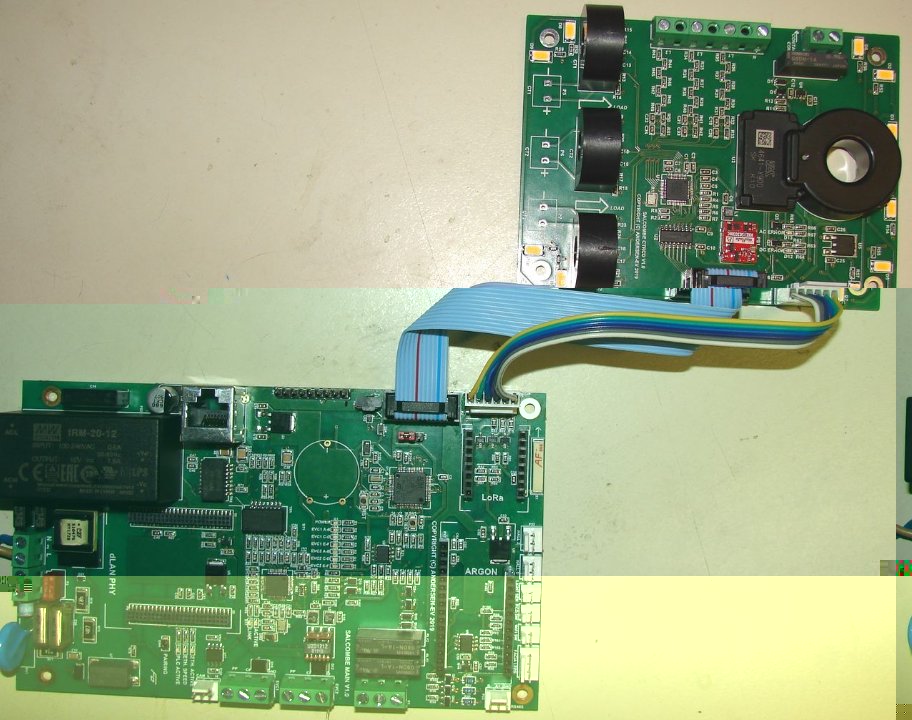
Here a picture, it is a dual EVSE + Energy Monitor + RCM-B , with LoRa + WiFi + Ethernet communication
- DSC01609.JPG (136.7 KiB) Viewed 9948 times
I agree with your proposed solution as I understand what said Ben.
I will try a C icon code, but I'm sure that will need your help
Thanks
Re: CAL_ADC component
Posted: Mon Dec 16, 2019 3:11 pm
by fotios
Benj wrote:I'm planning to add multi-adc support for the next major Flowcode release.
Also currently investigating DMA support for various peripherals including adc.
Hi Ben,
I really understand the case that it would be an enormous upgrade of FC.
I also was based on the... DMA of micro, as all other tasks excluded the ADC reading, are related to the LoRa or WiFi or Ethernet.
Don't forget please

the "nested interrupts" which is a historical feature of ST micros.
Thanks
Re: CAL_ADC component
Posted: Mon Dec 16, 2019 3:21 pm
by LeighM
Hi,
I have created some functions with C code icons, in attached project.
You should be able to export/import these macros into your project.
There are a few lines of code in Supplementary section which you will also need to copy into your project.
I tested that it compiles, but have not tested on target, so let me know if you have any problems.
Hope it helps,
Leigh
Re: CAL_ADC component
Posted: Fri Dec 27, 2019 10:35 am
by fotios
Hi Leigh
Sorry for the delayed reply.
I can confirm that the macros are working flawlessly on my actual hardware with the STM32F303RE.
You have configured the SMP register at 61.5 ADC clock cycles.
I checked the CAL_ADC file and that is related to the acquisition time of 40us.
Code: Select all
		else if (T_Charge > 40)
			MX_ADC_CH_CONF.SamplingTime = ADC_SAMPLETIME_61CYCLES_5;
From the manual:
TADC = TSMPL + TSAR = 61.5 + 12.5 = 74 ADC clock cycles.
The ADC clock = SYSclk / 4 = 24MHz / 4 = 6MHz or 0.166us.
The TSMPL = 0.166us * 61.5 = 10.21us.
The TSAR = 0.166us * 12.5 = 2.07us.
So the total conversion time is TADC = 10.2us + 2.07us = 12.28us.
The Pilot signal is a square wave with a fixed F=1KHz, and only the duty cycle (Dn) and the Vpeak can be changed.
The only value that is needed by the application, is to get the Vpeak.
If you need the Vavg, you can calculate it later with: Vavg = Vpeak * F * T where F=1000Hz and T=0.001s * Dn / 100.
I found that to get stable readings yet with a very small duty cycle (e.g. lower than 10%), the minimum number of samples should be greater than 50.
For 50 samples the required time is 50 * TADC = 614us.
I have enabled the TMR7 interrupt, with rollover F = 10Hz, which calls the ADC macro.
Then with a "While count < 50" loop I get only the ADC_Hi value which corresponds to the Vpeak.
To the present, the readings on the LCD of my hardware are very good.
Code: Select all
if (HAL_ADC_PollForConversion(&MX_ADC1_HANDLE, 100) == HAL_OK)
From the STM32F3 HAL driver manual:
HAL_ADC_PollForConversion
Function name. HAL_StatusTypeDef HAL_ADC_PollForConversion
(ADC_HandleTypeDef * hadc, uint32_t Timeout)
Function description. Wait for regular group conversion to be completed.
Parameters. hadc: ADC handle
Timeout: Timeout value in millisecond.
Return values. HAL: status
So the data transfer and processing are executed using blocking mode (polling, the non-blocking mode = interrupt or DMA) and the timeout=100ms.
Thanks a lot for your time and wishes for a very HAPPY NEW YEAR