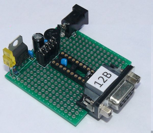
Always trying to get the best solution, I'm glad to announce an improved breadboard for 18 pins microchips.
The improved version is 12A and 12B.
The following Microchips can be used
PIC16F54, PIC16F1826, PIC16F1827, PIC16F1847, PIC16HV540, PIC16F627A, PIC16F628A, PIC16F818, PIC16F648A, PIC16F818, PIC16F819, PIC16F87, PIC16F88, PIC16F84A, PIC18F1220, PIC18F1230, PIC18F1320, PIC18F1330
with the remark that the numbering of the PIC18 deviates from the PIC16, but the ICSCP are always at the same pins.
The specifications of version 12B are
1) the board can be used with and without power supply (AC or DC)
2) A matrix of 16x18 whole is the standard, but not all of them are available.
- Column 1 and 18 are all GND
- Column 2 and 17 are +5V from rows 1-13
- Columns 8-11are mainly used by the microchip
- Columns 7 and 12 are connected with the corresponding microchip pins, except the ICSP pins of the microchip. These last pins can be connected or not depending on the 5 pins header (on top of the microchip)
3) Standard available
- ICSP for programming the chip, with automatically disconnecting electronic to the applicable pins
- sub-D 9 pins connector with all B0-B7 ports and GND, or B0-B6 ports , 5V+ and GND, depending on a 2 pins header (between the sub-D connector and the microchip)
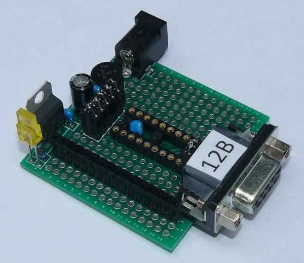
- Facultative a 16 pins LCD connector can be placed on column 3 (see picture)
- If the Sub-D connector is used for LCD, ports B6 and B7 are available for IOC, total 2 ports.
The specifications of version 12A are
All the same specifications as version 12B, except in version 12A ports A0-A3 are connected to sub-D pins 1-4. In version 12B ports B0-B3 are connected with sub-D pins 1-4.
That means that in version 12A ports B0-B3 are also available as IOC ports, total 6 ports.
Interested? Contact me.
With kind regards
Jan Lichtenbelt

- Breadboard V12B.jpg (77.25 KiB) Viewed 19824 times

- Breadboard V12B with 16 pins connector.jpg (73.8 KiB) Viewed 19824 times