Page 1 of 1
PWM and TMR2
Posted: Fri Sep 16, 2011 12:38 pm
by Jan Lichtenbelt
Hi All,
I try to change the duty time of the PWM output by measuring the time of an input pulse. This last will be done by means of TRM2 interrupt.
But now I get wrong PWM outputs with eg. only 100% duty, or a total wrong frequency. That seems like the registers of PWM are re-written. And that made me look more in detail in the PIC16F877A datasheet. This shows that PWM uses the TRM2 timer. And that means during PWM TRM2 can not be used for other applications.
Is this correct? Is there a solution?
With kind regards
Jan Lichtenbelt
Re: PWM and TMR2
Posted: Fri Sep 16, 2011 12:43 pm
by Benj
Hello Jan,
Yes the PWM peripheral uses the Timer 2 capture compare registers so you can only use one or the other in your program. Could you use timer 0 or timer 1 for your interrupt instead?
Re: PWM and TMR2
Posted: Fri Sep 16, 2011 12:56 pm
by Jan Lichtenbelt
I'm afraid TRM0 and TRM1 are to slow to measure a 1 msec pulse with some accuracy. What to do?
Can I read the TRM2 counter of PWM?
Re: PWM and TMR2
Posted: Fri Sep 16, 2011 1:05 pm
by Mikat
Hi.
Correct me if I am wrong, but the timer 1 should run at Fosc/4, so it is definitely fast and accurate enough.. At 4MHz chip clock, the timer 1 runs at 1µs increments, so the accuracy at 1ms pulse is 0.1%.
Flowcode just doesn't support reading the timer direct, so you have to do it by c-code like FCV_VARIABLE_H = tmr1h and FCV_VARIABLE_L = tmr1L, and the combine those two bytes to int..
Mika
Re: PWM and TMR2
Posted: Fri Sep 16, 2011 1:25 pm
by Jan Lichtenbelt
TRM1 interrupt frequency is maximum 75 Hz

- TRM1.jpg (36.39 KiB) Viewed 7579 times
But I found a solution: Using the ADC I can measure the input pulse duty time.
In the meanwhile I found out that the RC-circuit needed for ADC makes recording change in pulse duty times to slow.
This returns me to the original question: Is there a solution?
Thanks for help.
Kind regards
Jan
Re: PWM and TMR2
Posted: Fri Sep 16, 2011 2:34 pm
by Mikat
Hi.
i don't know exactly what are you doing, but if I had to measure pulse width, this is the way I maybe do it.
Connect the incoming pwm pulse both b0 and b1 rb0 int for rising edge and rb1 int for falling edge. When rb0 int occurs, write the tmr1 to 0 (c-code tmr1h = 0; tmr1l =0;) and when the rb1 int occurs read the timer 1 as i mentioned above... Then just little calculation depending the clock speed and timer1 confs (4MHz device clock and 1:1 prescaler gives the time direct in µs) gives the pulse time.
but I don't know how this suits in your application....
Mika
Re: PWM and TMR2
Posted: Fri Sep 16, 2011 3:08 pm
by Jan Lichtenbelt
Hi All,
I found a solution! With Flowcode you can produce easy PWM yourself with a very simple interrupt maco on TRM0 instead of TRM2.
Disadvantage:
Of coarse TRM0 is slower compared to TRM2, but some applications the high speed is not needed. The maximum speed of TRM0 is 19.2 kHz and with 100 counts a repetition time of 5.2 msec of the PWM is possible. For 255 counts this will be 13.3 msec.
Advantage:
As many as PWM you can make as you want, up to all outputs!!!
With kind regards
Jan Lichtenbelt
PS. Use the second version V2
Re: PWM and TMR2
Posted: Fri Sep 16, 2011 5:26 pm
by Spanish_dude
Flowcode's timer interrupt parameters supposes you do not set the timer register. (I don't know if there is a TMR1 register I never used that interrupt)
Nicolas
Re: PWM and TMR2
Posted: Fri Sep 16, 2011 5:50 pm
by Mikat
Spanish_dude wrote:Flowcode's timer interrupt parameters supposes you do not set the timer register. (I don't know if there is a TMR1 register I never used that interrupt)
Nicolas
Was that for my suggestion?
If it was I know that, but the thing was that measuring the pulse width, using directly timer1 counter, not the interrupt... Btw, at some point the flowcode doesn't set the timer1 control register correctly, at least I need to manually configure it (yes timer1 have control register t1con).
The software pwm could be done via other timers too, if you use direct access to the timer, and interrupt, the pwm frequency could be quite high, over kHz, but there must be carefully that the software has time to get out the interrupt macro before next interrupt occurs (the pwm is so fast that in big duty cycles, the next int triggers before the software gets out of the pin dowm macro) .. That subject was topic somewhere, if somebody is interested at sw pwm...
Mika
Re: PWM and TMR2
Posted: Fri Sep 16, 2011 7:25 pm
by jgu1
Hi Jan!
Very interested project. I've looked at it and have not quite figured out yet. Would you please give an example where you adjust the pulse width in via analog input.

Thank you in advance.
greeting
Jorgen
Re: PWM and TMR2
Posted: Fri Sep 16, 2011 8:32 pm
by Jan Lichtenbelt
Dear Jorgen,
An other way of measuring the on duty time is by integration the input signal. And then digitalise the input by means of ADC.
Integration is very easy. Just a RC circuit. However, the disadvantage of this method is that the RC-time must be about 10 times the period time of the input signal. If that is not a problem, than you can use this method.
Succes,
Jan Lichtenbelt
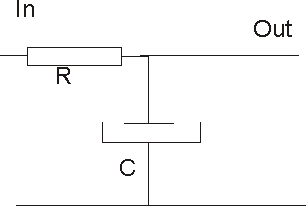
- RC-Integrator.jpg (7.06 KiB) Viewed 7548 times
Re: PWM and TMR2
Posted: Fri Sep 16, 2011 10:08 pm
by Spanish_dude
@ Mikat : I actually said that for Jan, I should have mentioned it, my bad

.
Re: PWM and TMR2
Posted: Sat Sep 17, 2011 9:14 am
by Jan Lichtenbelt
Please find an improved macro PWM version3, as example to produce as much as PWM's you like. The PWM are produced by means of TRM0 instead of TRM2. TRM2 will be still available of other fast processes.
Succes
Jan
Re: PWM and TMR2
Posted: Sun Sep 18, 2011 10:45 am
by jgu1
Hi Jan!
Thanks for your reply.
I think you misunderstood. I will not measure the PWM input. But I want to adjust the PWM output, by analog input by a potm. in YOUR examble. I know about the hardware.
Best regard
Jørgen.