Component: Simulation 7 Seg (Misc)
| Author | Matrix Ltd |
| Version | 1.0 |
| Category | Misc |
Contents
Simulation 7 Seg component
Simulated single digit seven segment display. LED colour can be changed in properties.
Component Source Code
Please click here to download the component source project: FC_Comp_Source_LED_7Seg_Single_Sim.fcfx
Please click here to view the component source code (Beta): FC_Comp_Source_LED_7Seg_Single_Sim.fcfx
Detailed description
No detailed description exists yet for this component
Examples
Each segment will require a current limiting resistor.
This LED Calculator tool is a good resource for calculating the correct LED series protection resistor.
Basic Multiplexing
Only one of the four 7-segment LEDs can be enabled at a time so we need a way of multiplexing the output so that we can display a number on all four LEDs. To do this we switch between LED outputs at fairly high speed and persistence of vision allows the display to appear fixed and constant.
This example demonstrates a very basic loop to display a four digit number multiplexed across four 7segment displays.
![]() Quad 7Segment Display Example
Quad 7Segment Display Example
Timer Based Multiplexing
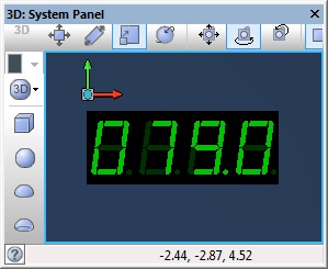
This example demonstrates a timer interrupt to display a four digit number multiplexed across four 7segment displays. The timer interrupt takes care of updating the display leaving our program free to count up in 100ms increments.
![]() Quad 7Segment Display Example 2
The panel should show the simulation run time down to the current tenth of a second.
Quad 7Segment Display Example 2
The panel should show the simulation run time down to the current tenth of a second.
Stop Watch
This next example uses a timer interrupt to multiplex between the displays and a second timer interrupt to count the passing of time allowing for accurate timings. Using four single 7-seg components we create a timer capable of monitoring time from 0.0 to 999.9 seconds in multiples of 100ms. The second timer interrupt flags to the main when the count value has changed allowing the heavier calculations to extract the digits from the counter to be done outside of the high speed interrupt routine and therefore maintain accurate timing.
Switches connected to Port D allow for the timer to be started, stopped and reset.
![]() 7Segment Timer
7Segment Timer
Macro reference
ClearDigit
SegControl
| SegControl | |
| Direct control over the display segments | |
| data | |
| Return | |
ShowDigit
Property reference
| Properties | |
| Colors | |
| LED On Color | |
| Color when an LED is turned on. | |
| LED Off Color | |
| Color when an LED is turned off. | |
| Bezel Color | |
| Color of the plastic package housing the LEDs | |
