Component: Fast Fourier Transform (FFT) (DSP Operators)
| Author | Matrix Ltd |
| Version | 1.2 |
| Category | DSP Operators |
Contents
Fast Fourier Transform (FFT) component
Provides a way of converting a buffer full of time domain data into frequency domain data. The output of the FFT is a set of frequency bins which correspond to the frequencies present in the signal. The number of frequency bins is equal to half the input buffer size with each bin being responsible for a portion of the frequency up to 1/2 the nyquist.
Component Source Code
Please click here to download the component source project: FC_Comp_Source_DSP_FFT.fcfx
Please click here to view the component source code (Beta): FC_Comp_Source_DSP_FFT.fcfx
Detailed description
No detailed description exists yet for this component
Examples
Example takes two adjustable frequency sine wave inputs and combines them and then passes the collection of 256 samples to the FFT function which produces 128 individual frequency banks which are then plotted from left (lowest frequency) to right (highest frequency) using an XY chart component.
Frequency output for a set of data
Frequency banks can be worked out by using the sample frequency and buffer size. The number of frequency banks is equal to the number of samples divided by 2 minus 1. We subtract the one because bank 0 is always empty and so can be discounted.
FrequencyBanks = (SampleCount / 2) - 1
The frequency ranges present inside a bank can be worked out as follows.
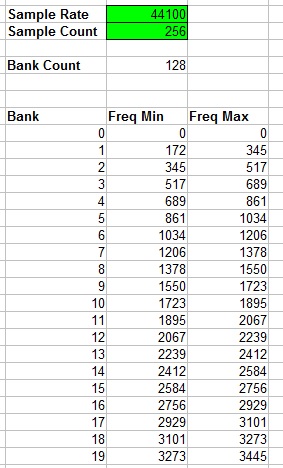
FreqMin = ((SampleRate / 2) / (SampleCount / 2)) * Bank
FreqMax = ((SampleRate / 2) / (SampleCount / 2)) * (Bank + 1)
For example if we sample at 10KHz and collect 256 samples then frequency bank 10 would represent any frequencies in the range of 390.6Hz to 429.7Hz.
Here is a spreadsheet document that will calculate the frequencies present in each bank. The highlighted green fields are editable and will update the rest of the values.
File:FFT Frequency Bank Calculator.xls
Macro reference
FFT
QueueData
ReadFrequencyBank

