Component: LED Base (Outputs: General)
| Author | Matrix Ltd |
| Version | 1.3 (Development) |
| Category | Outputs: General |
Contents
 LED Base component
Base for creating LEDs and other on/off visual indicators. Choose a 'Target Object' that will change colour when the pin changes; if multiple objects must change color, group them, and target the group. When 'Auto off color" is selected, changing the 'on color' will automatically choose an off color by reducing the on-color intensity.
This component can be used as a base to create child components
The following components all inherit the traits of LED Base:
Examples
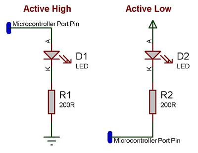
LEDs can be wired either active high or active low. The LED components should each have a property allowing you to configure which LED type your using.
An active high LED will light when the microcontroller pin is outputting a logic 1 and be off when the microcontroller pin is outputting a logic 0 or in input mode.
An active low LED will light when the microcontroller pin is outputting a logic 0 and be off when the microcontroller pin is outputting a logic 1 or in input mode.
The series resistor can be on either side of the LED and acts to protect the LED from damage due to excess current. The value of resistor used can be changed based on the brightness of the LED and power consumption.
This LED Calculator tool is a good resource for calculating the correct LED series protection resistor.
Downloadable macro reference
TurnOn
Turn the LED off.
Parameters
- This macro has no parameters
Return value
- This call does not return a value
TurnOff
Turn the LED on.
Parameters
- This macro has no parameters
Return value
- This call does not return a value
Simulation macro reference
This component does not contain any simulation macros
Property reference
Pin
This property is of type Single digital pin and can be referenced with the variable name pin.
Chip pin to connect the LED to.
Polarity
This property is of type Fixed list of ints and can be referenced with the variable name polarity.
Active High: Pin true -> On color, Pin false -> Off color
Active Low: Pin true -> Off color, Pin false -> On color
Target Object
This property is of type Panel object and can be referenced with the variable name target_object.
Set a target object to be the illuminating part of the LED.
To change the colour of multiple objects, group them first, then target the group.
On Color
This property is of type Color picker and can be referenced with the variable name on_color.
The color of the LED when it is turned on.
Off Color
This property is of type Color picker and can be referenced with the variable name off_color.
The color of the LED when it is turned off.
Auto Off Color
This property is of type True or false and can be referenced with the variable name auto_off.
When this is selected, the off color is automatically set to a darker version of the on color.
