Page 1 of 2
1x 74HC595/TPIC6B595 via SPI interface, driving multiplexed 4x 7-segment display
Posted: Wed Feb 11, 2026 2:07 pm
by andeug
Hi,
I am working on building a digital clock that uses an STM32 Nucleo and a TPIC6B595 (instead of a 74HC595), with MOSFETs driving each digit.
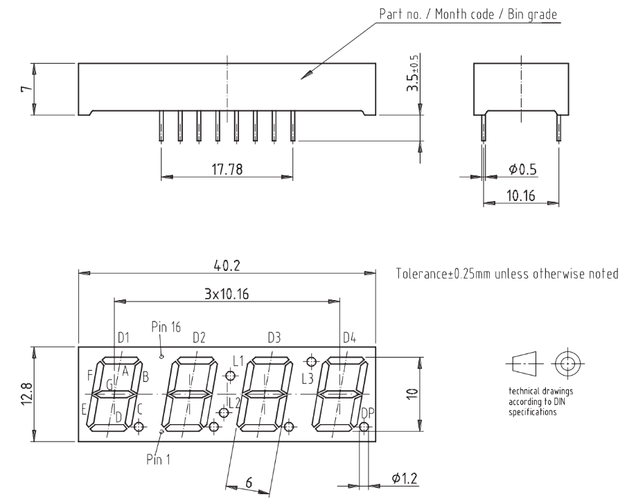
The display is a Vishay TDCR1050M, common anode, for which I am enclosing its datasheet below:
I am using this particular display because it has a digit for degrees Celsius (L3), a column (L1 + L2) for blinking seconds, plus DP for an active alarm. Also, the display and such setup have fewer pins, as it is optimized for a multiplexed setup.
- Screenshot 2026-02-11 at 15.05.57.png (116.92 KiB) Viewed 4382 times
How do I use this kind of display in Flowcode 11, when the default component for a 7-segment display already contains 74HC595 shift registers for each digit, rather than a single shift register (TPIC6B595) for all the digits, and multiplexing for each digit? I do not know how to use multiplexing - can someone please show me via a Flowcode file how it should be done?
Thank you,
Andreas
Re: 1x 74HC595/TPIC6B595 via SPI interface, driving multiplexed 4x 7-segment display
Posted: Fri Feb 13, 2026 10:15 am
by mnfisher
Multiplexing - you need to 'turn on' the individual segments for some of the time - rapidly switching between the different digits by connecting the common (anode or cathode)
Have a look at
https://www.flowcode.co.uk/forums/viewt ... g&start=10
Martin
Re: 1x 74HC595/TPIC6B595 via SPI interface, driving multiplexed 4x 7-segment display
Posted: Sat Feb 21, 2026 8:58 pm
by andeug
Does anyone know how to create a schematic of the display for my clock project in Flowcode?
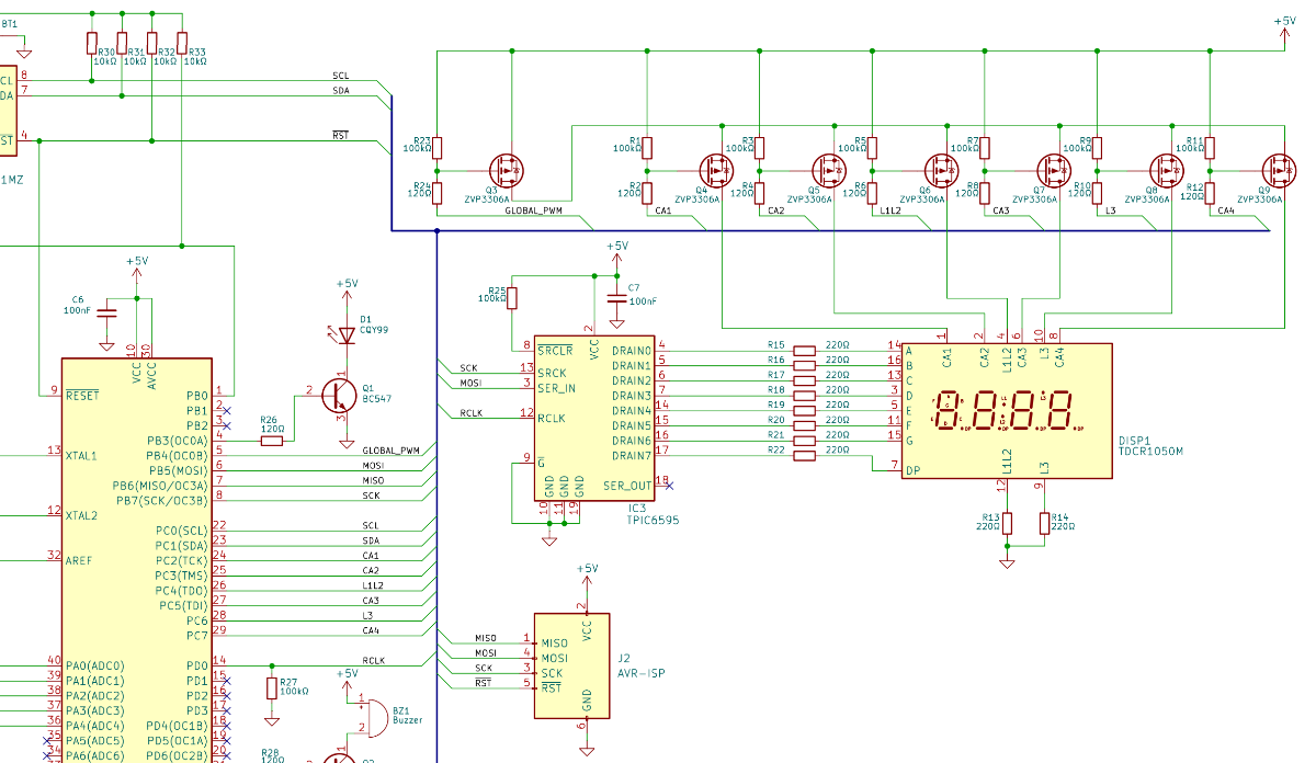
- Screenshot 2026-02-21 215921.png (199.8 KiB) Viewed 3948 times
There is no component for the common anode display setup I am using.
Re: 1x 74HC595/TPIC6B595 via SPI interface, driving multiplexed 4x 7-segment display
Posted: Sat Feb 21, 2026 9:29 pm
by chipfryer27
Hi
Not sure I understand your question as you seem to already have a schematic diagram showing all connections.
If you mean do we know offhand the internal components of the display module and how they are connected, probably not. However some manufacturers including Vishay often provide a schematic as part of their datasheet, so check there.
Regards
Re: 1x 74HC595/TPIC6B595 via SPI interface, driving multiplexed 4x 7-segment display
Posted: Sun Feb 22, 2026 8:50 am
by andeug
My question is how do I work with this display schematic in Flowcode. Unfortunately there is no display component that represents this schematic, and maybe there is a workaround which I can use…
Re: 1x 74HC595/TPIC6B595 via SPI interface, driving multiplexed 4x 7-segment display
Posted: Sun Feb 22, 2026 12:38 pm
by chipfryer27
Hi
In other posts you mentioned about the 6595 and I questioned the need for such, as you will only ever be drawing a fraction of it's capability. Any of the existing shift-registers (e.g. 8574) that are supported would be able to handle your requirement with ease.
From the other posts you mention that you intend to use the 1050 due to it's extra "segments" L1 - L3, and I informed that you would either need to allocate two or three extra pins to control these segements independently (only two if L1 and L2 are on at same time), or if pins are unavailable allocate another 8-bit register purely for these segments. I see you have commoned L1 & L2 and are using dedicated pins.
Again in a previous posts I outlined the "rough steps" to displaying
https://www.flowcode.co.uk/forums/viewt ... 009#p23009
Although not having your shift-register to test with you could most likely use any of the following to clock out data:-
1) SPI Master components with RCLK connected to CS. Examples of using such in WiKi.
2) I2C with you manually controlling RCLK. Examples of using such in WiKi
3) Simply create your own routine looping to send 8-bits, using Output icons to control pin status and appropriate delays.
Again as per previous post have CA1 - 4 On/Off based on a timer (e.g. 20mS but I have no idea of value to use).
Send your bits for digit-1
Enable CA1
Manually set L1 - L3
Delay (go do something else)
Repeat for digits 2 - 4
Regards
Re: 1x 74HC595/TPIC6B595 via SPI interface, driving multiplexed 4x 7-segment display
Posted: Tue Feb 24, 2026 10:04 pm
by mnfisher
I had a play with this...
This is a first idea - and as Iain says using CS as RCLK seems to work well...
I use an interrupt to multiplex the displays - the character set is a rough attempt with QA connected to segment A, QB to seg B etc)
I found an interrupt rate of 244Hz worked nicely (each digit refreshed at ~60Hz) - these displays are not very breadboard friendly! - I used resistors on the 4 digit select pins - instead of on the segment pins (so brightness varies slightly).
I used a F3561AH 4 digit display and a Sn74HC595 shift register. I ignore the DP - but it could be connected to QH.
I used an ATMega328P (Arduino Uno) but it should work okay on other MCUs - the proviso being that SPI can be used in an interrupt. On the Arduino it only works with SPI using the software channel (and it might be as well just to bit-bang this rather than using SPI).
I also connected OE (output enable) - this could possibly just be pulled to ground.
It would also be possible - originally I intended to do this - to use multiple shift registers to do 8, 12 or more digits. Commons would be connected to 1,5... and 2,6 etc and select the appropriate digits to output.. The wiring was too daunting tho'

Martin
Re: 1x 74HC595/TPIC6B595 via SPI interface, driving multiplexed 4x 7-segment display
Posted: Tue Feb 24, 2026 10:05 pm
by mnfisher
Pins for CA0 (probably should be CA1 ?) - CA3 etc are in properties. It's all Flowcode - but doesn't attempt to simulate (although you can look at what is being sent to the shift registers and the common pins in multiplex)
Martin
Re: 1x 74HC595/TPIC6B595 via SPI interface, driving multiplexed 4x 7-segment display
Posted: Tue Feb 24, 2026 10:12 pm
by mnfisher
The 'trace' showing the 'common' pins.
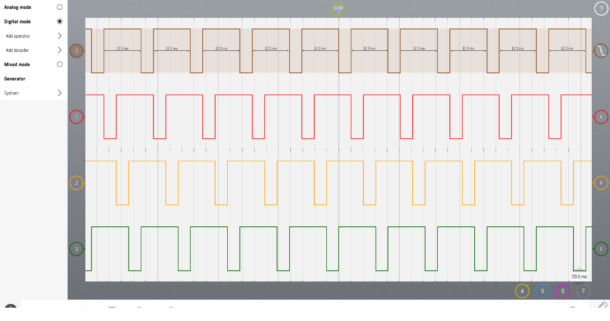
- LabNation_Screenshot48.png (163.83 KiB) Viewed 3780 times
Re: 1x 74HC595/TPIC6B595 via SPI interface, driving multiplexed 4x 7-segment display
Posted: Tue Feb 24, 2026 10:23 pm
by mnfisher
A rather busy breadboard !
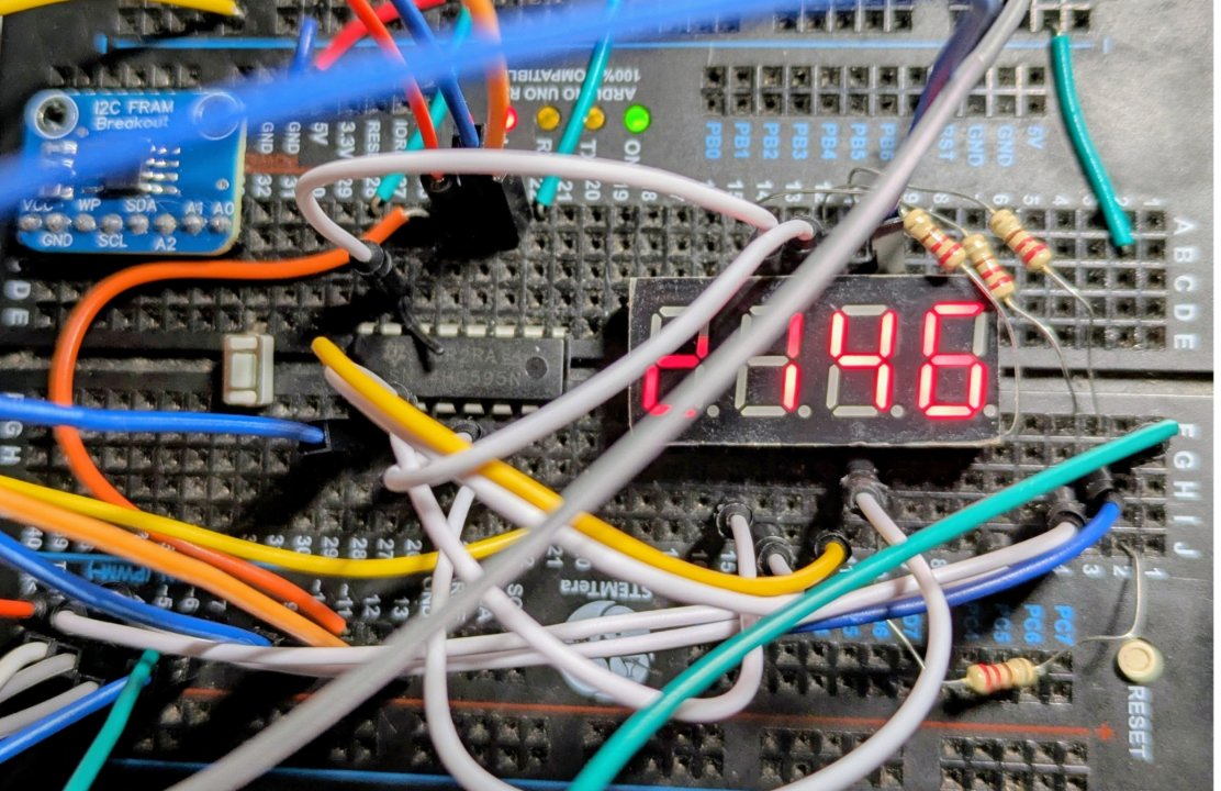
- disp_led.jpg (185.2 KiB) Viewed 3774 times