Difference between revisions of "Component: DAC (AD5662) (Analog Output)"
| (11 intermediate revisions by the same user not shown) | |||
| Line 15: | Line 15: | ||
16-bit external DAC connected to the microcontroller using SPI. | 16-bit external DAC connected to the microcontroller using SPI. | ||
| − | ==Component | + | ==Component Source Code== |
| − | + | Please click here to download the component source project: [https://www.flowcode.co.uk/wiki/componentsource/FC_Comp_Source_DAC_AD5662.fcfx FC_Comp_Source_DAC_AD5662.fcfx] | |
| + | |||
| + | Please click here to view the component source code (Beta): [https://www.flowcode.co.uk/FlowchartView/?wfile=componentsource/FC_Comp_Source_DAC_AD5662.fcfx FC_Comp_Source_DAC_AD5662.fcfx] | ||
==Detailed description== | ==Detailed description== | ||
| + | |||
| + | |||
| + | |||
| + | |||
| + | |||
| + | |||
| + | |||
| + | |||
| + | |||
| + | |||
| + | |||
| + | |||
| + | |||
| + | |||
| + | |||
| + | |||
| Line 47: | Line 65: | ||
==Examples== | ==Examples== | ||
| + | |||
| + | |||
| + | |||
| + | |||
| + | |||
| + | |||
| + | |||
| + | |||
| + | |||
| + | |||
| + | |||
| + | |||
| + | |||
| + | |||
| + | |||
| + | |||
| Line 63: | Line 97: | ||
{{Fcfile|AD5662_Demo.fcfx|AD5662_Demo}} | {{Fcfile|AD5662_Demo.fcfx|AD5662_Demo}} | ||
| − | |||
| + | |||
| + | |||
| + | |||
| + | |||
| + | |||
| + | |||
| + | |||
| + | |||
| + | |||
| + | ==Macro reference== | ||
| + | |||
| + | ===Initialise=== | ||
{| class="wikitable" style="width:60%; background-color:#FFFFFF;" | {| class="wikitable" style="width:60%; background-color:#FFFFFF;" | ||
|- | |- | ||
| width="10%" align="center" style="background-color:#D8C9D8;" align="center" | [[File:Fc9-comp-macro.png]] | | width="10%" align="center" style="background-color:#D8C9D8;" align="center" | [[File:Fc9-comp-macro.png]] | ||
| − | | width="90%" style="background-color:#D8C9D8; color:#4B008D;" | ''' | + | | width="90%" style="background-color:#D8C9D8; color:#4B008D;" | '''Initialise''' |
|- | |- | ||
| − | | colspan="2" | | + | | colspan="2" | Initialise the SPI bus ready for communications, |
|- | |- | ||
| − | |||
| − | |||
| − | |||
| − | |||
| − | |||
|- | |- | ||
| width="10%" align="center" style="border-top: 2px solid #000;" | [[File:Fc9-void-icon.png]] - VOID | | width="10%" align="center" style="border-top: 2px solid #000;" | [[File:Fc9-void-icon.png]] - VOID | ||
| Line 83: | Line 123: | ||
| + | ===OutputDAC=== | ||
{| class="wikitable" style="width:60%; background-color:#FFFFFF;" | {| class="wikitable" style="width:60%; background-color:#FFFFFF;" | ||
|- | |- | ||
| width="10%" align="center" style="background-color:#D8C9D8;" align="center" | [[File:Fc9-comp-macro.png]] | | width="10%" align="center" style="background-color:#D8C9D8;" align="center" | [[File:Fc9-comp-macro.png]] | ||
| − | | width="90%" style="background-color:#D8C9D8; color:#4B008D;" | ''' | + | | width="90%" style="background-color:#D8C9D8; color:#4B008D;" | '''OutputDAC''' |
| + | |- | ||
| + | | colspan="2" | Outputs a value to the DAC, | ||
| + | |- | ||
|- | |- | ||
| − | | | + | | width="10%" align="center" | [[File:Fc9-u16-icon.png]] - UINT |
| + | | width="90%" | Output | ||
|- | |- | ||
| + | | colspan="2" | Range: 0-65535 / 0=0V / 65535=VCC | ||
|- | |- | ||
| width="10%" align="center" style="border-top: 2px solid #000;" | [[File:Fc9-void-icon.png]] - VOID | | width="10%" align="center" style="border-top: 2px solid #000;" | [[File:Fc9-void-icon.png]] - VOID | ||
| width="90%" style="border-top: 2px solid #000;" | ''Return'' | | width="90%" style="border-top: 2px solid #000;" | ''Return'' | ||
|} | |} | ||
| − | |||
| − | |||
| Line 104: | Line 148: | ||
| width="10%" align="center" style="background-color:#D8C9D8;" | [[File:Fc9-prop-icon.png]] | | width="10%" align="center" style="background-color:#D8C9D8;" | [[File:Fc9-prop-icon.png]] | ||
| width="90%" style="background-color:#D8C9D8; color:#4B008D;" | '''Properties''' | | width="90%" style="background-color:#D8C9D8; color:#4B008D;" | '''Properties''' | ||
| + | |- | ||
| + | |- | ||
| + | | width="10%" align="center" style="background-color:#EAE1EA;" | [[File:Fc9-conn-icon.png]] | ||
| + | | width="90%" style="background-color:#EAE1EA; color:#4B008D;" | SPI Properties | ||
|- | |- | ||
|- | |- | ||
| Line 136: | Line 184: | ||
| colspan="2" | Chip Select / Slave Select Pin Master Mode: General purpose output pin used to select the remote SPI device. Slave Mode: Hardware chip select pin input used to select the SPI device. | | colspan="2" | Chip Select / Slave Select Pin Master Mode: General purpose output pin used to select the remote SPI device. Slave Mode: Hardware chip select pin input used to select the SPI device. | ||
|- | |- | ||
| − | + | | width="10%" align="center" style="background-color:#EAE1EA;" | [[File:Fc9-conn-icon.png]] | |
| − | + | | width="90%" style="background-color:#EAE1EA; color:#4B008D;" | Simulation | |
| − | |||
| − | |||
| − | |||
| − | |||
| − | |||
| − | |||
| − | |||
| − | |||
| − | |||
| − | |||
| − | |||
| − | |||
| − | |||
| − | |||
| − | |||
| − | |||
| − | |||
| − | | width="10%" align="center" style="background-color:# | ||
| − | | width="90%" style="background-color:# | ||
|- | |- | ||
|- | |- | ||
Latest revision as of 13:09, 7 February 2023
| Author | Matrix TSL |
| Version | 1.0 |
| Category | Analog Output |
Contents
DAC (AD5662) component
16-bit external DAC connected to the microcontroller using SPI.
Component Source Code
Please click here to download the component source project: FC_Comp_Source_DAC_AD5662.fcfx
Please click here to view the component source code (Beta): FC_Comp_Source_DAC_AD5662.fcfx
Detailed description
Overview
The AD5662 is a 3V/5V general purpose SPI compatible, high-resolution digital to analog converter (DAC), capable of generating a rail-to-rail voltage output.
With 16-Bit resolution, the AD5662 is capable of finely tuning the voltage output across 65,536 steps, with an individual step voltage of 5/65536 = 0.0000763 volts DC.
The AD5662 requires an external reference voltage to set the output range of the DAC.
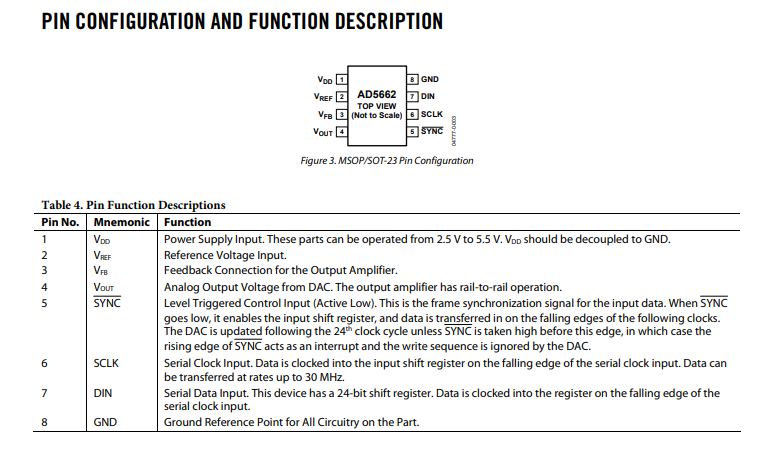
Pin reference from the datasheet:
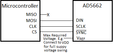
Circuit Diagram
Examples
This example reads a potentiometer that is connected across the supply voltage. The output from the DAC should mimic the voltage that's across ADC pin & GND.
Macro reference
Initialise
| Initialise | |
| Initialise the SPI bus ready for communications, | |
| Return | |
OutputDAC
| OutputDAC | |
| Outputs a value to the DAC, | |
| Output | |
| Range: 0-65535 / 0=0V / 65535=VCC | |
| Return | |

