| Author
|
Matrix Ltd
|
| Version
|
1.8
|
| Category
|
Alphanumeric
|
LCD (Adafruit, 16x2) component
Adafruit OLED LCD display capable of displaying 2 lines of 16 characters.
Component Pack
DISPLAYS
Detailed description
No detailed description exists yet for this component
Examples
Connections
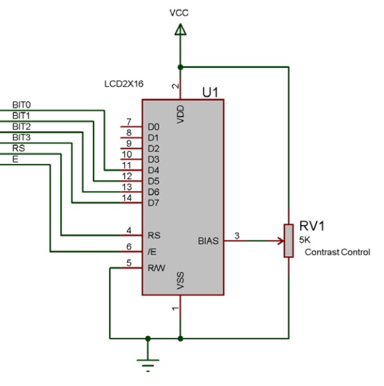
For the LCDs to work with the Flowcode LCD component they need to be connected up in 4-bit data mode.
The 4 data signals actually go to the upper data nibble on the LCD as shown below.

A simple example that shows how to use some common functions.
 Adafruit LCD Example
Downloadable macro reference

|
Clear
|
| Clears the entire contents of the display.
|
 - VOID - VOID
|
Return
|

|
PrintString
|
| Breaks down a string of text and sends it to the LCD via the private RawSend(byte, mask) macro
|
 - STRING - STRING
|
Text
|
|
|
 - VOID - VOID
|
Return
|

|
PrintAscii
|
| Takes the ascii value for a character and prints the character
|
 - BYTE - BYTE
|
character
|
| Holds an ascii value.
|
 - VOID - VOID
|
Return
|

|
PrintNumber
|
| Based on v5 macro, will allow you to print a number. This is limited to a signed-INT, -32768 to 32767
|
 - INT - INT
|
Number
|
|
|
 - VOID - VOID
|
Return
|

|
RAMWrite
|
| Modifies the internal memory of the LCD to allow for up to 8 customised characters to be created and stored in the device memory
|
 - BYTE - BYTE
|
Index
|
| Values 0 to 7
|
 - BYTE - BYTE
|
d0
|
|
|
 - BYTE - BYTE
|
d1
|
|
|
 - BYTE - BYTE
|
d2
|
|
|
 - BYTE - BYTE
|
d3
|
|
|
 - BYTE - BYTE
|
d4
|
|
|
 - BYTE - BYTE
|
d5
|
|
|
 - BYTE - BYTE
|
d6
|
|
|
 - BYTE - BYTE
|
d7
|
|
|
 - VOID - VOID
|
Return
|

|
ClearLine
|
| Clears a single line on the display before moving the cursor back to the start of the line to allow new data to be displayed.
|
 - BYTE - BYTE
|
Line
|
|
|
 - VOID - VOID
|
Return
|

|
Cursor
|
| Moves the cursor on the LCD Display
|
 - BYTE - BYTE
|
x
|
|
|
 - BYTE - BYTE
|
y
|
|
|
 - VOID - VOID
|
Return
|

|
Command
|
| Use this method/macro to send a specific command to the LCD. Refer to the Matrix Multimedia EB006 datasheet for a list of supported instructions. For Non-Matrix LCD's refer to the manufacturers datasheet.
|
 - BYTE - BYTE
|
instruction
|
| Send a defined command to the LCD Screen. See datasheet for supported commands.
|
 - VOID - VOID
|
Return
|

|
ScrollDisplay
|
| Scrolls the display left or right by a number of given positions.
|
 - BYTE - BYTE
|
Position
|
| Holds the number of positions to shift the display
|
 - BYTE - BYTE
|
direction
|
| 0 = left, 1 = right
|
 - VOID - VOID
|
Return
|

|
Start
|
| Startup routine required by the hardware device. Automatically clears the display when complete.
|
 - VOID - VOID
|
Return
|
Property reference

|
Properties
|

|
Rows
|
| Number of vertical characters that can be shown on the display
|

|
Columns
|
| Number of horizontal characters that can be shown on the display
|

|
Background Color
|
| Simulation only property to control the background colour, on the hardware the colour is fixed.
|

|
Line Color
|
| Simulation only property to control the line colour, on the hardware the colour is fixed.
|

|
Text Color
|
| Simulation only property to control the text colour, on the hardware the colour is fixed.
|

|
Font
|
| Simulation only property to control the display font, on the hardware the font is fixed.
|

|
Connections
|

|
Data 0 (11)
|
| Data pin 0 connects to data pin 4 on the hardware
|

|
Data 1 (12)
|
| Data pin 1 connects to data pin 5 on the hardware
|

|
Data 2 (13)
|
| Data pin 2 connects to data pin 6 on the hardware
|

|
Data 3 (14)
|
| Data pin 3 connects to data pin 7 on the hardware
|

|
Register Select (4)
|
| Register select pin, determines if the incoming value is a command or a data byte
|

|
Read / Write (5)
|
| Read / Write pin determines the data direction
|

|
Enable (6)
|
| Enable pin, used to clock data in and out of the device.
|

|
Simulations
|
