Difference between revisions of "Component: LED (EB004) (E-blocks 1)"
(XML import - Pre 8.0 release) |
|||
| Line 19: | Line 19: | ||
==Examples== | ==Examples== | ||
| − | |||
| + | |||
| + | |||
| + | LEDs can be wired either active high or active low. The LED components should each have a property allowing you to configure which LED type your using. | ||
| + | |||
| + | [[File:LED_Active.jpg]] | ||
| + | |||
| + | |||
| + | An active high LED will light when the microcontroller pin is outputting a logic 1 and be off when the microcontroller pin is outputting a logic 0 or in input mode. | ||
| + | |||
| + | |||
| + | An active low LED will light when the microcontroller pin is outputting a logic 0 and be off when the microcontroller pin is outputting a logic 1 or in input mode. | ||
| + | |||
| + | |||
| + | The series resistor can be on either side of the LED and acts to protect the LED from damage due to excess current. The value of resistor used can be changed based on the brightness of the LED and power consumption. | ||
| + | |||
| + | |||
| + | This LED Calculator tool is a good resource for calculating the correct LED series protection resistor. | ||
| + | |||
| + | [https://www.digikey.co.uk/en/resources/conversion-calculators/conversion-calculator-led-series-resistor LED Resistor Calculator Tool] | ||
==Downloadable macro reference== | ==Downloadable macro reference== | ||
Revision as of 16:01, 10 February 2022
| Author | Matrix TSL |
| Version | 1.1 (Release) |
| Category | E-blocks 1 |
Contents
 LED (EB004) component
An LED matrix made up of standard PCB mount 5mm LEDs.
Examples
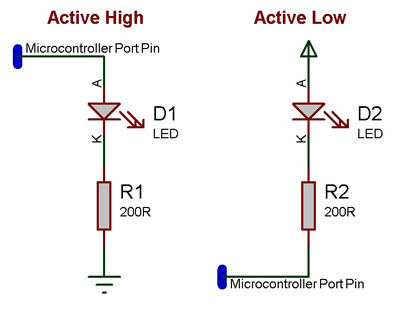
LEDs can be wired either active high or active low. The LED components should each have a property allowing you to configure which LED type your using.
An active high LED will light when the microcontroller pin is outputting a logic 1 and be off when the microcontroller pin is outputting a logic 0 or in input mode.
An active low LED will light when the microcontroller pin is outputting a logic 0 and be off when the microcontroller pin is outputting a logic 1 or in input mode.
The series resistor can be on either side of the LED and acts to protect the LED from damage due to excess current. The value of resistor used can be changed based on the brightness of the LED and power consumption.
This LED Calculator tool is a good resource for calculating the correct LED series protection resistor.
Downloadable macro reference
BarGraph
Turns on the first N elements of the array - for generating bar graph metes etc.
Parameters
- BYTE Length
- How many items to light up.
Return value
- This call does not return a value
LEDOn
Turn on the selected LED.
Parameters
- BYTE Index
- Index of the LED to turn on.
Return value
- This call does not return a value
AllOn
Turns on all elements
Parameters
- This macro has no parameters
Return value
- This call does not return a value
LEDOff
Turn off the selected led.
Parameters
- BYTE Index
- Index of the LED to turn on.
Return value
- This call does not return a value
PointGraph
Turns on the Indexed LED and turns all others off.
Does nothing if the index is out of range.
Parameters
- BYTE Index
- The LED to show.
Return value
- This call does not return a value
WriteValue
Write a number which is presented on the LEDs in binary.
Parameters
- BYTE Value
- Provide a value to be written to the LEDs in binary
Return value
- This call does not return a value
AllOff
Turns off all elements
Parameters
- This macro has no parameters
Return value
- This call does not return a value
Simulation macro reference
This component does not contain any simulation macros
Property reference
Output Mode
This property is of type Fixed list of ints and can be referenced with the variable name port.
Choose a single port for all LEDs, or to allocate them to arbitrary pins.
Port
This property is of type Digital port byte and can be referenced with the variable name PortByte.
No additional information
