Component: UART (RS232) (Comms: Interface)
| Author | Matrix Ltd |
| Version | 3.0 |
| Category | Comms: Interface |
Contents
- 1 UART (RS232) component
- 2 Component Source Code
- 3 Detailed description
- 4 Examples
- 5 Macro reference
- 5.1 ChangeHWBaud
- 5.2 Initialise
- 5.3 ReceiveBinary16Bit
- 5.4 ReceiveBinary32Bit
- 5.5 ReceiveBinaryFloat
- 5.6 ReceiveByteArray
- 5.7 ReceiveChar
- 5.8 ReceiveFloat
- 5.9 ReceiveHexNumber
- 5.10 ReceiveINTArray
- 5.11 ReceiveNumber
- 5.12 ReceiveString
- 5.13 SendBinary16Bit
- 5.14 SendBinary32Bit
- 5.15 SendBinaryFloat
- 5.16 SendByteArray
- 5.17 SendChar
- 5.18 SendFloat
- 5.19 SendHexNumber
- 5.20 SendINTArray
- 5.21 SendNumber
- 5.22 SendString
- 6 Property reference
UART (RS232) component
Low level routines for controlling or interacting with a standard asyncronous serial interface. On a microcontroller the interface will be the onboard UART which will need voltage level shifting using a max2323 to become RS232 compatible. See the EB015 RS232 E-block for details.
Component Source Code
Please click here to download the component source project: FC_Comp_Source_RS232.fcfx
Please click here to view the component source code (Beta): FC_Comp_Source_RS232.fcfx
Detailed description
Overview
The RS232 component is in fact nothing more than a TTL level asynchronous serial communications bus which basically means that there is no clock signal. Instead the data is sent out at a precise data rate specified by the Baud which is represented in bits per second. Both devices need to be set to the same rate to allow communications to work correctly.
There are two signals which make up the asynchronous serial connection: RX and TX. The receive RX signal is used for incoming data and the transmit TX signal is used for outgoing data. When connecting two devices together it is important to connect the TX of one device to the RX of the other and visa versa. When inactive the bus defaults to having the TX signal held in the high state. Each data byte sent then starts with a low signal for 1 period of the baud rate to signify that data is to follow.
Each RS232 transaction consists of a start bit (low) for a single clock cycle followed by data made up of 7/8/9 clock cycles followed by a stop bit (high) for a single clock cycle.
TTL
By default the RS232 component will provide TTL asynchronous serial data which is best suited for a single device to single device data connection on the same circuit board. An example might be a GSM modem or GPS module. The TTL signals are normally at VCC when the bus is idle and toggles between VCC and Ground when sending data.
RS232
By adding a driver chip such as a MAX2323 the TTL signals can be upgraded to RS232 which is best suited for single device to single device mid range off board communications. The RS232 signals replace the voltages VCC with +12V and GND with -12V to allow for better noise rejection in noisy environments.
RS485
By adding a driver chip such as a MAX3078 the TTL signals can be upgraded to RS485 which is best suited for master to multiple slave type mid range off board communications.
Auto Baud
Some devices feature an auto baud functionality and is commonly triggered by sending a known data byte to the device before any other data is sent allowing the correct baud to be worked out.
Examples
Transmit
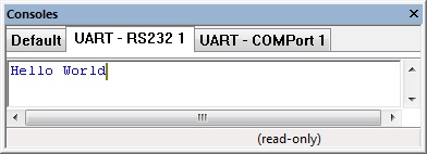
This example transmits a string "Hello World".
![]() RS232_Example1
The Console window shows the data as it is sent and received.
RS232_Example1
The Console window shows the data as it is sent and received.
Receive
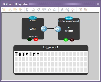
This example receives a character and outputs it to the LCD, an injector has been added to allow you to type data into the console.
![]() RS232_Example2
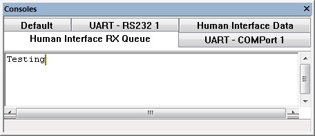
The Console window has tabs for the human interface data injector allowing you to type in data that will be received by the component.
RS232_Example2
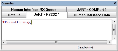
The Console window has tabs for the human interface data injector allowing you to type in data that will be received by the component.
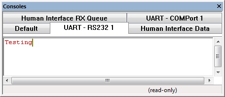
Again the RS232 console tabs reflect the data as it is sent and received.
LCD showing received data.
Transmit and Receive
This example echoes back any data that is received allowing a nice sanity check when connecting an embedded device to a PC or other source of communications.
![]() RS232_Example3
Again the RS232 console tabs reflect the data as it is sent and received.
RS232_Example3
Again the RS232 console tabs reflect the data as it is sent and received.
UART Bridge
This example allows a microcontroller with two UART peripherals to receive data one one UART and transmit on the other and visa versa in a reliable manner using interrupts. Note that this method will only work with hardware UART channels. A software UART could be done in a similar way using a falling edge type interrupt on the UART RX pin to trigger the receive function.
![]() RS232_Example4
RS232_Example4
COM Port
The COM port property allows you to attach the RS232 component to a COM port on your PC during simulation allowing real world hardware such as RS232, Bluetooth, GPS to work with the simulation.
Injector
The Injector property allows you to select an injector component on the panel for use in the simulation. The human interface injector can be used to inject typed in data via the console window and can be seen in examples 2 and 3 above.
There are other pre-made injectors to allow you to do various aspects from simulating a generic AT terminal to simulating a specific remote device.
Macro reference
ChangeHWBaud
| ChangeHWBaud | |
| Changes the hardware UART baud rate allowing for dynamic speed changes. | |
| NewBaud | |
| 0=1200, 1=2400, 2=4800, 3=9600, 4=19200, 5=38400, 6=57600, 7=115200, 8=250000 | |
| Return | |
Initialise
| Initialise | |
| Sets up the RS232 peripheral, must be called at the start of your program or at least before you start calling any other RS232 macros. | |
| Return | |
ReceiveBinary16Bit
ReceiveBinary32Bit
ReceiveBinaryFloat
ReceiveByteArray
ReceiveChar
| ReceiveChar | |
| Attempts to receive a single packet from the UART interface. | |
| Timeout | |
| Time to wait in milliseconds for valid data before returning, 0=Dont wait, 255=Wait forever. | |
| Return | |
ReceiveFloat
ReceiveHexNumber
ReceiveINTArray
ReceiveNumber
ReceiveString
SendBinary16Bit
| SendBinary16Bit | |
| Sends out a 16-bit binary value split across two bytes. | |
| Value | |
| MSBfirst | |
| 0=Least significant byte first, 1=Most significant byte first | |
| Return | |
SendBinary32Bit
| SendBinary32Bit | |
| Sends out a 32-bit binary value split across four bytes. | |
| Value | |
| MSBfirst | |
| 0=Least significant byte first, 1=Most significant byte first | |
| Return | |
SendBinaryFloat
| SendBinaryFloat | |
| Sends out a 32-bit binary floating point value split across four bytes. | |
| Value | |
| MSBfirst | |
| 0=Least significant byte first, 1=Most significant byte first | |
| Return | |
SendByteArray
| SendByteArray | |
| Transmits an array of bytes via the UART peripheral | |
| Data | |
| Data to transmit | |
| NumBytes | |
| Number of bytes to send from the array | |
| Return | |
SendChar
| SendChar | |
| Sends out a single packet from the UART interface. | |
| Char | |
| Return | |
SendFloat
| SendFloat | |
| Sends out a floating point number as an ASCII String from the UART interface. | |
| Number | |
| Return | |
SendHexNumber
SendINTArray
SendNumber
| SendNumber | |
| Sends out a number as an ASCII String from the UART interface. | |
| Number | |
| Return | |
SendString
| SendString | |
| Sends out a string of bytes from the UART interface. | |
| Data | |
| Return | |

