Creating Project
Contents
Old Versions
This page is current for Flowcode v11 and later. Earlier versions can be found below:
| Flowcode v10 |
| Flowcode v9 |
| Flowcode v8 |
Create the Project
Create a new project by either selecting 'New Project' from the 'File' menu (File > New Project), pressing Ctrl+N on the keyboard or clicking on the NEW PROJECT button on the Start Page.
This will initiate a step-by-step process to guide you through creating a new project.
Project Types
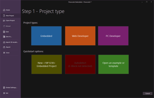
The first screen allows selection of the project type
- Embedded projects are designed to be downloaded and run on a microcontroller
- Web Developer creates a project that runs in a web browser
- PC Developer creates a project that run on a Windows PC
Three other options exist:
- Quickstart - choose the same chip type as the last embedded project
- Autodetect - connected E-Blocks 3 boards will be autodetected, including attached downstream boards
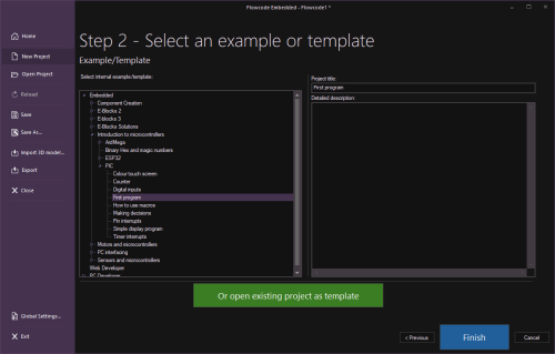
- Example/Template - examples and templates can be loaded using this option
Choosing a new Embedded project will initiate a step-by-step process to select the chip device and ensure it is configured correctly, as described below.
Choosing to open an example or template will open the example/template screen.
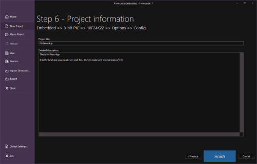
Any other option will open the final screen in the process when a project name and description can be entered before finishing the process and creating a new project.
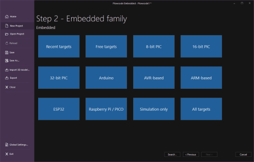
Embedded Family
Flowcode supports many embedded devices and to make chip selection easier, the step-by-step process begins by selecting an embedded family.
Recently chosen or Free targets can be selected, rather than selecting an actual family.
The "Search..." button can be used to quickly find a device.
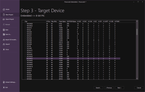
Target Device
The next stage of the process allows the actual chip to be selected. Sub-families in the list can be expanded or collapsed if necessary by right-clicking in the list.
The "Search..." button can be used to find a specific device, or the columns can be clicked to arrange the list of targets by various features such as the number of ADC pins or the Flash memory size.
Project Options
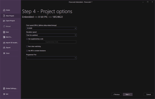
Several project options can be changes in this screen.
Clock Speed
Flowcode needs to know how fast you are clocking your chip so that it can implement the delay function with the correct delay time.
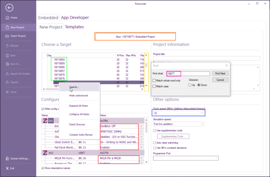
You can alter the chip clock speed at any time by selecting Build > Project Options and entering the correct value of your clock circuit by entering the value within the Clock Speed at the middle right of the project Options window (blue rectangle).
It should be noted that the clock speed affects things like delays, it does not control the hardware speed.
If using an external oscillator, the hardware speed is controlled by a crystal or a resonator
If using an internal oscillator, in a lot of cases, depending on the target, a C code block with an OSCCON or OSCFRQ value will be required - See Internal Oscillator and IntOsc Helper component
Supplementary Code
There are several ways to incorporate C code into a Flowcode project. One way is to use the Code icon and another is to add supplementary code, which can be added here.
Other Options
- Auto clear watchdog
Some devices have a watchdog timer that resets the chip unless it is periodically reset. This setting allows Delay icons to reset the watchdog timer.
- Use #ifdef in constant decisions
This is an advanced setting that can make the code smaller when decisions in the code that resolve to a constant.
- Programmer Port
Some devices, such as Arduino and ESP boards, are reprogrammed via a serial connection (often via USB). The serial port used to reprogram these devices is set here.
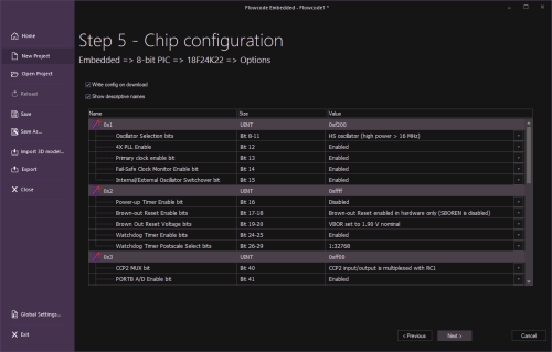
Chip Configuration
Many embedded devices can be configured in different ways - e.g. with a different type of oscillator setup. This screen allows these configurations to be selected.
Please note that it is important to check the configuration before downloading to a chip.
Please ensure that the chip type and oscillator type are correct for your program as these are the main source of user problems.
Some of the more popular devices will have a default configuration which assumes a few of the more popular settings.
As a rule of thumb any feature you are not specifically using should be disabled.
Leaving any of the following enabled will likely cause issues for your application: low voltage programming, watchdog timer, extended CPU.
Configuring the chip for PICmicros
Clicking on the Configure tab from within the Project Options calls up the Configuration page, which allows you to customize settings for your current chip.
The configuration page can be used to:
Set the oscillator type required
Enable/disable advanced features such as brown out, watchdog timers, low voltage programming, read protection etc.
If you are using Flowcode for the very first time, or have changed development boards, you may need to check the options to set which board you are using.
Manually configuring the chip for PICmicros
See Selecting Compiler Options (PICmicro) for help with switching off the default configuration options that use PPP.
Once you have disabled the default configuration options you can enter your own configuration data. For the PICmicro this data will be sent to the chip every time you perform a compile to chip operation.
An example configuration word for the PIC16 series is
0x2007, 0x3FFC
The 0x2007 is the location in memory of the configuration word and the 0x3FFC is the configuration word itself.
An example set of configuration words for the PIC18 series is
0x300000, 0x00
0x300001, 0x22
0x300002, 0x0D
0x300003, 0x0E
0x300004, 0x00
0x300005, 0x00
0x300006, 0x80
0x300007, 0x00
0x300008, 0x0F
0x300009, 0xC0
0x30000A, 0x0F
0x30000B, 0xE0
0x30000C, 0x0F
0x30000D, 0x40
Configuring the Chip for AVRs
The chip can be configured from the Configure option in the chip menu.
Please note that it is important to check the configuration before downloading to a chip.
Configuration settings for individual devices may be represented by 1, 2 or 3 bytes
The function of many of the individual configuration bits are also device dependent.
The data sheet for the relevant target device should be consulted before sending configuration data.
The default setting is configured to send the hex value 0xdf (223 decimal) to parameter location 0
The parameter locations are:
0 = Fuse High Byte (hfuse)
1 = Fuse Low byte (lfuse)
2 = Extended fuse Byte (efuse)
An example of 3 bytes of configuration data is shown below
OK and Send
Save the configuration data and send to the target device
OK
Confirm the configuration data but do not send to the target device
Note: Configuration memory might have a lower endurance than program memory. Only send configuration data when changes are required.
AVR's can also become locked if incorrect configuration settings are loaded so take care when transferring the settings to a device.
Project Info
Examples and Templates
Selecting device type from within Flowcode
You can change devices at any time by selecting Build > Project Options. Simply select the chip type from the 'Choose a Target' (green rectangle), Or right-click on any target and select 'Search' then enter partial characters, e.g 18877. Whatever target device is selected, it will appear on the Target button at the top for you to click (orange rectangle). If you are changing from one microcontroller to another, Flowcode will check that all the commands and components in your flowchart are supported by the new microcontroller. Flowcode will advise you of any potential problems.
