Using the Data Recorder
Introduction
Flowcode includes a Data Recorder ideal for testing your applications in both hardware and simulation.
It works alongside Ghost Technology to allow users to monitor signals in real time using In-Circuit-Test. It can also be used in simulation mode, though timing of signals is not accurate when using simulation. In simulation, it allows the user to see the results and values from raw data and components such as dials and measures. This data allows you to monitor Variables and the state of the various signals plotted to various channels.
The Data Recorder is very useful for analyzing data as it can accurately display information to identify patterns in the data as well as the speed data is being displayed at. Components such as the DSP range will automatically create their own Data Recorder channels, allowing for very simple yet powerful means of monitoring and debugging the system.
How to use
Adding streams
Streams are separated via two types: user streams and program streams.
User streams
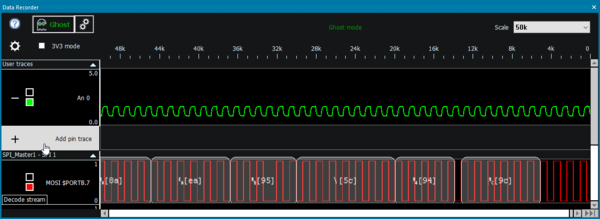
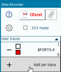
User streams are simple streams that allow you to easily monitor the value of a digital or analog pin. They can be added by simply clicking the “Add pin trace” button on the Data Recorder itself and selecting the appropriate digital or analog pin.
This method of adding streams is recommended if you are using Ghost Technology to view live pin data from your Matrix hardware.
Program streams
Program streams are added by components or by flowchart icons in your program. For some components, simply adding it to the 2d or 3d panel causes a program stream to appear in the Data Recorder. These streams are then controlled by the component itself and will be removed automatically when appropriate.
Here, we will give an example of creating your own program stream using flowchart icons.
Creating a stream
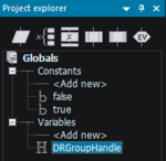
To create a new stream group you first need to create a global “Handle” type variable to store the reference to the stream group. This is basically a unique number which used to refer to that specific group of streams in the Data Recorder. To do this, open the Project Explorer window and select the “Globals” tab. Next, under the “Variables” portion of the tree view, double-click “Add New” from the menu. In the “Create a New Variable” dialogue that pops up give the variable a meaningful name such as “DRGroupHandle”, then switch the variable type to “Object handle” and click “OK”. You should then get an Object handle variable appearing in the Project Explorer window.
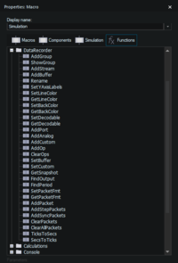
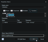
Next, we need to assign the handle variable with a value by calling the Flowcode API. To do this we add a Simulation Macro (link) icon to the “Main” flowchart. Then we double-click the icon on the flowchart to edit the icon's properties. Inside the icon property window we first need to ensure that the “Functions” tab is selected and then scroll down to the “DataRecorder” section before clicking the + icon to see all the API calls related to the Data Recorder’s functionality.
The AddGroup function call creates a new named group of streams on the Data Recorder. The return value of the function call requires a handle type variable. You should set this to the name of the variable we have created previously (“DRGroupHandle” in this example). Type a name that you want into the parameter field, (such as “Test Group”).
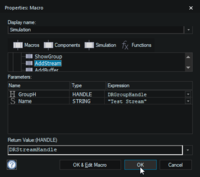
The AddStream function call adds a new named stream to the group on the Data Recorder. The return value of the function call is a handle type variable. We will have to create a new global object handle type variable to store this. This handle must be unique for each single stream so you must use a new object handle variable for every program stream that you create on the Data Recorder.
When we run the simulation the new group will be created on the Data Recorder ready for data to be streamed in.
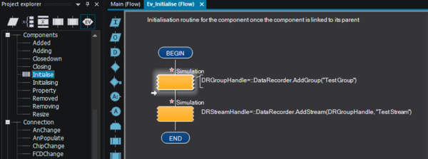
If you are creating your own Flowcode component, you can move these from the Main macro to the component initialise event macro so that the group and stream are created automatically when the component is added to a program. This is the way that components such as the DSP based components add their data to the console window.
Note that a group with no valid stream handles will not show up on the Data Recorder window, in order to avoid potential unnecessary clutter.
Setting the handle variable to the value of 0 using a Calculation icon or calling the System -> DeleteHandle API call will remove the group or stream from the Data Recorder window.
Adding a digital pin or port to a program stream
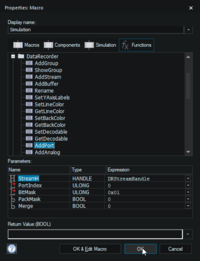
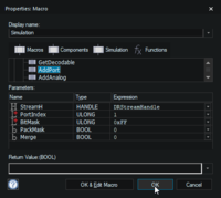
A digital pin or port can be assigned to a stream object handle by using the AddPort function call. The function requires:
- the stream object handle,
- the port index where PORTA is 0, PORTB is 1 etc.
- the BitMask parameter. This is a binary AND mask which selects which bits of the port will be available on the stream.
- The PackMask parameter. Setting this to 1 will move all the active bits together if necessary.
- The merge parameter. This allows you to add multiple ports or pins to a single stream. Set this to 1 if you are adding a digital pin or port to an existing stream that already contains data, and you wish to combine the data.
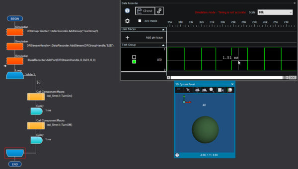
To monitor a single pin (e.g. Port A, Pin 0) with an LED connected, we can call the AddPort function like this.
Here is a simple program to toggle the LED with the signal being replicated on the Data Recorder.
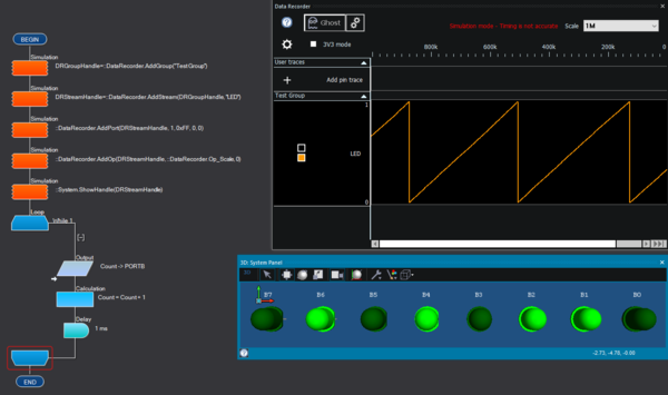
To monitor a full port (e.g. Port B) with a LED Array connected, we can call the AddPort function like this.
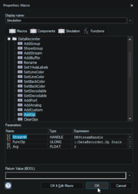
We then scale the stream to get the value in the range of 0-1 by calling the AddOp function like this.
Here is a simple program to generate a digital counter on Port B, with the signal being replicated on the Data Recorder. The ShowHandle function allows the Data Recorder window to appear automatically without the user having to manually open the window.
Adding an analogue pin to a program stream
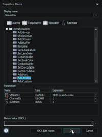
An analogue pin can be assigned to a stream object handle by using the AddAnalog function call. The function requires:
- the stream object handle,
- the analogue channel index where An0 is 0, An1 is 1 etc.
- the Subtract parameter. This allows you to add or subtract multiple analogue signals on a single stream. Set this to 1 if you are adding an analog pin to an existing stream that already contains data, and you wish to subtract the data. Alternatively set it to 0 if you wish to add/combine the data.
To monitor a single analogue pin (e.g. pin An0), with a potentiometer connected, we can call the AddAnalog function like this.
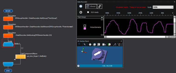
Here is a simple program to track the value of pin An0, based on the position of the potentiometer.
Adding a custom value to a program stream
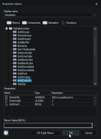
Custom values are those that do not correspond directly to pins or ports. A custom value can be assigned to a stream object handle by using the AddCustom function call. The function requires:
- the stream object handle,
- the custom channel index 0-31. These act as “slots” in which to store your data. Select a value that is not used by any other custom streams.
- the Subtract parameter. This allows you to add or subtract multiple custom channels on a single stream. Set this to 1 if you are adding a custom channel to an existing stream that already contains data, and you wish to subtract the data. Alternatively set it to 0 if you wish to add/combine the data.
To create a single custom stream, we can call the AddCustom function like this.
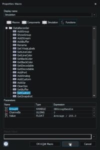
The data for a custom channel cannot come from a digital or analogue channel automatically. Instead we have to manually pass the data to the custom channel. This is done by using the SetCustom function call. The value passed should be a floating-point real number in the range between 0 and 1 (so to convert a byte variable we would have to divide by the value 255.0.)
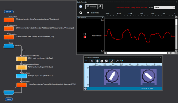
Here is a simple program which creates a custom stream, adds custom channel 0 to it, and then continually:
- tracks the values of two analogue input signals
- calculates the average between the two readings.
- sends the data to custom channel 0, which appears on the Data Recorder in the created stream.
Interacting with streams
You can change the time span that is being examined by using the drop down on the top-right of the window. Alternatively, you can use your mouse’s scroll wheel. Using the scroll wheel is even more powerful as it allows you to zoom directly over a particular point of interest. Stream heights can be modified by dragging the bottom border of the left hand pane for the relevant stream. Colours used for rendering can be modified on the fly directly, by clicking the top square next to the stream name (for the stream background colour), and the bottom square next to the stream name (for the stream waveform/foreground colour)
Hovering your mouse over the stream will show you the time interval between the two peaks that surround the cursor. Note that in simulation mode, this timing is not accurate.
Packet Decoding
Communications buses can be decoded to work out what values a bus is sending out and receiving.
Supported Busses:
- UART (RS232, GSM, GPS, Modbus, Bluetooth, ...)
- SPI (SPI Master, FAT, EEPROM, RTC, ...)
- I2C (I2C Master, Accelerometer, EEPROM, RTC, ...)
Packet decoding is available for certain program streams added by components. The button for decoding becomes available when the relevant communication component is added to the panel.
Decoding is then done by clicking the decode stream button on the appropriate stream. Streams can be decoded regardless of whether the Data Recorder is running in simulation or Ghost mode.
