|
|
| (17 intermediate revisions by 2 users not shown) |
| Line 14: |
Line 14: |
| ==Servo Motor (Tower Pro 9g) component== | | ==Servo Motor (Tower Pro 9g) component== |
| Small size 9g servo motor suitable for control by the 'Servo Controller' component. Use the 'Link to...' property to attach other objects to the rotor for emulating mechanical systems. Send a virtual PWM signal to the servo by selecting it as a target of the 'Servo Controller' component. | | Small size 9g servo motor suitable for control by the 'Servo Controller' component. Use the 'Link to...' property to attach other objects to the rotor for emulating mechanical systems. Send a virtual PWM signal to the servo by selecting it as a target of the 'Servo Controller' component. |
| | |
| | ==Component Source Code== |
| | |
| | Please click here to download the component source project: [https://www.flowcode.co.uk/wiki/componentsource/FC_Comp_Source_Micro_Servo_9G.fcfx FC_Comp_Source_Micro_Servo_9G.fcfx] |
| | |
| | Please click here to view the component source code (Beta): [https://www.flowcode.co.uk/FlowchartView/?wfile=componentsource/FC_Comp_Source_Micro_Servo_9G.fcfx FC_Comp_Source_Micro_Servo_9G.fcfx] |
|
| |
|
| ==Detailed description== | | ==Detailed description== |
| | |
| | |
| | |
| | |
| | |
| | |
| | |
| | |
| | |
| | |
| | |
| | |
| | |
| | |
| | |
| | |
| | |
| | |
| | |
| | |
| | |
| | |
|
| |
|
| ''No detailed description exists yet for this component'' | | ''No detailed description exists yet for this component'' |
| Line 22: |
Line 50: |
|
| |
|
|
| |
|
| Please note that the servo motor template and child components require the Servo Controller component to control them.
| |
|
| |
|
|
| |
|
| ===Controlling a servo with an analogue input===
| |
|
| |
|
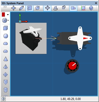
| This example reads the value of the analogue potentiometer and uses this to set the position of the servo motor.
| |
| {{Fcfile|Single servo motor control.fcfx|Servo Example 1}}
| |
| The Servo controller is linked to the standard servo component but this could be linked to any object on the panel.
| |
|
| |
|
| [[File:ServoLink.jpg]]
| |
|
| |
|
|
| |
|
| ===Creating a multi-axis actuator using servo motors===
| |
|
| |
|
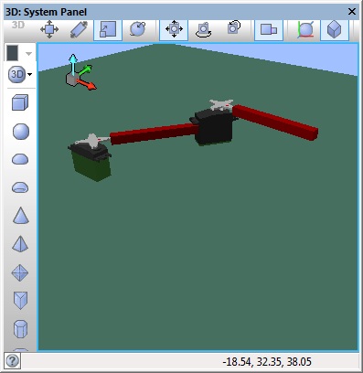
| This example links two servo motors together using panel primitive objects and groups.
| |
| {{Fcfile|Servo Demo.fcfx|Servo Example 2}}
| |
| The Servo controller can handle up to 8 motors and is used to control both of the standard servo components on the panel.
| |
|
| |
|
| [[File:LinkedServo.jpg]]
| |
|
| |
|
| ==Downloadable macro reference==
| |
|
| |
|
| {| class="wikitable" style="width:60%; background-color:#FFFFFF;"
| |
| |-
| |
| | width="10%" align="center" style="background-color:#D8C9D8;" align="center" | [[File:Fc9-comp-macro.png]]
| |
| | width="90%" style="background-color:#D8C9D8; color:#4B008D;" | '''Forward'''
| |
| |-
| |
| | colspan="2" | Drives both motors of the formula flowcode forwards with the power specified.
| |
| |-
| |
| |-
| |
| | width="10%" align="center" | [[File:Fc9-u8-icon.png]] - BYTE
| |
| | width="90%" | Power
| |
| |-
| |
| | colspan="2" |
| |
| |-
| |
| | width="10%" align="center" style="border-top: 2px solid #000;" | [[File:Fc9-void-icon.png]] - VOID
| |
| | width="90%" style="border-top: 2px solid #000;" | ''Return''
| |
| |}
| |
|
| |
|
|
| |
|
| {| class="wikitable" style="width:60%; background-color:#FFFFFF;"
| |
| |-
| |
| | width="10%" align="center" style="background-color:#D8C9D8;" align="center" | [[File:Fc9-comp-macro.png]]
| |
| | width="90%" style="background-color:#D8C9D8; color:#4B008D;" | '''ReadLineSensor'''
| |
| |-
| |
| | colspan="2" | Returns the digital value from the line sensor specified.
| |
| |-
| |
| |-
| |
| | width="10%" align="center" | [[File:Fc9-u8-icon.png]] - BYTE
| |
| | width="90%" | Sensor
| |
| |-
| |
| | colspan="2" |
| |
| |-
| |
| | width="10%" align="center" style="border-top: 2px solid #000;" | [[File:Fc9-u8-icon.png]] - BYTE
| |
| | width="90%" style="border-top: 2px solid #000;" | ''Return''
| |
| |}
| |
|
| |
|
|
| |
|
| {| class="wikitable" style="width:60%; background-color:#FFFFFF;"
| |
| |-
| |
| | width="10%" align="center" style="background-color:#D8C9D8;" align="center" | [[File:Fc9-comp-macro.png]]
| |
| | width="90%" style="background-color:#D8C9D8; color:#4B008D;" | '''SpinRight'''
| |
| |-
| |
| | colspan="2" | Spins the formula flowcode on the spot in a clockwise direction as seen from above.
| |
| |-
| |
| |-
| |
| | width="10%" align="center" | [[File:Fc9-u8-icon.png]] - BYTE
| |
| | width="90%" | Power
| |
| |-
| |
| | colspan="2" |
| |
| |-
| |
| | width="10%" align="center" style="border-top: 2px solid #000;" | [[File:Fc9-void-icon.png]] - VOID
| |
| | width="90%" style="border-top: 2px solid #000;" | ''Return''
| |
| |}
| |
|
| |
|
|
| |
|
| {| class="wikitable" style="width:60%; background-color:#FFFFFF;"
| |
| |-
| |
| | width="10%" align="center" style="background-color:#D8C9D8;" align="center" | [[File:Fc9-comp-macro.png]]
| |
| | width="90%" style="background-color:#D8C9D8; color:#4B008D;" | '''CheckIR'''
| |
| |-
| |
| | colspan="2" | Checks to see if a IR sensor is within the master threshold distance.
| |
| |-
| |
| |-
| |
| | width="10%" align="center" | [[File:Fc9-u8-icon.png]] - BYTE
| |
| | width="90%" | Sensor
| |
| |-
| |
| | colspan="2" |
| |
| |-
| |
| | width="10%" align="center" style="border-top: 2px solid #000;" | [[File:Fc9-u8-icon.png]] - BYTE
| |
| | width="90%" style="border-top: 2px solid #000;" | ''Return''
| |
| |}
| |
|
| |
|
|
| |
|
| {| class="wikitable" style="width:60%; background-color:#FFFFFF;"
| |
| |-
| |
| | width="10%" align="center" style="background-color:#D8C9D8;" align="center" | [[File:Fc9-comp-macro.png]]
| |
| | width="90%" style="background-color:#D8C9D8; color:#4B008D;" | '''ReadIRSensor'''
| |
| |-
| |
| | colspan="2" | Reads the analogue value from the specified IR distance sensor.
| |
| |-
| |
| |-
| |
| | width="10%" align="center" | [[File:Fc9-u8-icon.png]] - BYTE
| |
| | width="90%" | Sensor
| |
| |-
| |
| | colspan="2" |
| |
| |-
| |
| | width="10%" align="center" style="border-top: 2px solid #000;" | [[File:Fc9-u16-icon.png]] - UINT
| |
| | width="90%" style="border-top: 2px solid #000;" | ''Return''
| |
| |}
| |
|
| |
|
|
| |
|
| {| class="wikitable" style="width:60%; background-color:#FFFFFF;"
| |
| |-
| |
| | width="10%" align="center" style="background-color:#D8C9D8;" align="center" | [[File:Fc9-comp-macro.png]]
| |
| | width="90%" style="background-color:#D8C9D8; color:#4B008D;" | '''SetMotors'''
| |
| |-
| |
| | colspan="2" | Sets the speed and direction of the Formula Flowcode motors.
| |
| |-
| |
| |-
| |
| | width="10%" align="center" | [[File:]] -
| |
| | width="90%" | Left_Power
| |
| |-
| |
| | colspan="2" | Valid Range = -255 to 255
| |
| |-
| |
| | width="10%" align="center" | [[File:]] -
| |
| | width="90%" | Right_Power
| |
| |-
| |
| | colspan="2" | Valid Range = -255 to 255
| |
| |-
| |
| | width="10%" align="center" style="border-top: 2px solid #000;" | [[File:Fc9-void-icon.png]] - VOID
| |
| | width="90%" style="border-top: 2px solid #000;" | ''Return''
| |
| |}
| |
|
| |
|
|
| |
|
| {| class="wikitable" style="width:60%; background-color:#FFFFFF;"
| | Please note that the servo motor template and child components require the Servo Controller component to control them. |
| |-
| | |
| | width="10%" align="center" style="background-color:#D8C9D8;" align="center" | [[File:Fc9-comp-macro.png]]
| | |
| | width="90%" style="background-color:#D8C9D8; color:#4B008D;" | '''Reverse'''
| | ===Controlling a servo with an analogue input=== |
| |-
| | |
| | colspan="2" | Drives both motors of the formula flowcode backwards with the power specified.
| | This example reads the value of the analogue potentiometer and uses this to set the position of the servo motor. |
| |- | | {{Fcfile|Single servo motor control.fcfx|Servo Example 1}} |
| |-
| | The Servo controller is linked to the standard servo component but this could be linked to any object on the panel. |
| | width="10%" align="center" | [[File:Fc9-u8-icon.png]] - BYTE
| | |
| | width="90%" | Power
| | [[File:ServoLink.jpg]] |
| |-
| | |
| | colspan="2" |
| | |
| |-
| | ===Creating a multi-axis actuator using servo motors=== |
| | width="10%" align="center" style="border-top: 2px solid #000;" | [[File:Fc9-void-icon.png]] - VOID
| | |
| | width="90%" style="border-top: 2px solid #000;" | ''Return''
| | This example links two servo motors together using panel primitive objects and groups. |
| |}
| | {{Fcfile|Servo Demo.fcfx|Servo Example 2}} |
| | The Servo controller can handle up to 8 motors and is used to control both of the standard servo components on the panel. |
| | |
| | [[File:LinkedServo.jpg]] |
|
| |
|
|
| |
|
| {| class="wikitable" style="width:60%; background-color:#FFFFFF;"
| |
| |-
| |
| | width="10%" align="center" style="background-color:#D8C9D8;" align="center" | [[File:Fc9-comp-macro.png]]
| |
| | width="90%" style="background-color:#D8C9D8; color:#4B008D;" | '''WaitForSwitch'''
| |
| |-
| |
| | colspan="2" | Waits for the specified switch to be pressed.
| |
| |-
| |
| |-
| |
| | width="10%" align="center" | [[File:Fc9-u8-icon.png]] - BYTE
| |
| | width="90%" | Switch
| |
| |-
| |
| | colspan="2" |
| |
| |-
| |
| | width="10%" align="center" style="border-top: 2px solid #000;" | [[File:Fc9-void-icon.png]] - VOID
| |
| | width="90%" style="border-top: 2px solid #000;" | ''Return''
| |
| |}
| |
|
| |
|
|
| |
|
| {| class="wikitable" style="width:60%; background-color:#FFFFFF;"
| |
| |-
| |
| | width="10%" align="center" style="background-color:#D8C9D8;" align="center" | [[File:Fc9-comp-macro.png]]
| |
| | width="90%" style="background-color:#D8C9D8; color:#4B008D;" | '''ReadLDR'''
| |
| |-
| |
| | colspan="2" | Reads the current audio signal level from the on-board light sensor.
| |
| |-
| |
| |-
| |
| | width="10%" align="center" style="border-top: 2px solid #000;" | [[File:]] -
| |
| | width="90%" style="border-top: 2px solid #000;" | ''Return''
| |
| |}
| |
|
| |
|
|
| |
|
| {| class="wikitable" style="width:60%; background-color:#FFFFFF;"
| |
| |-
| |
| | width="10%" align="center" style="background-color:#D8C9D8;" align="center" | [[File:Fc9-comp-macro.png]]
| |
| | width="90%" style="background-color:#D8C9D8; color:#4B008D;" | '''WriteLEDs'''
| |
| |-
| |
| | colspan="2" | Allows control of all 8-LEDs on the front of the Formula Flowcode.
| |
| |-
| |
| |-
| |
| | width="10%" align="center" | [[File:Fc9-u8-icon.png]] - BYTE
| |
| | width="90%" | LED_Byte
| |
| |-
| |
| | colspan="2" |
| |
| |-
| |
| | width="10%" align="center" style="border-top: 2px solid #000;" | [[File:Fc9-void-icon.png]] - VOID
| |
| | width="90%" style="border-top: 2px solid #000;" | ''Return''
| |
| |}
| |
|
| |
|
|
| |
|
| {| class="wikitable" style="width:60%; background-color:#FFFFFF;"
| |
| |-
| |
| | width="10%" align="center" style="background-color:#D8C9D8;" align="center" | [[File:Fc9-comp-macro.png]]
| |
| | width="90%" style="background-color:#D8C9D8; color:#4B008D;" | '''Initialise'''
| |
| |-
| |
| | colspan="2" | Starts up the formula flowcode PWM for motor control and performs the wait for button press
| |
| |-
| |
| |-
| |
| | width="10%" align="center" style="border-top: 2px solid #000;" | [[File:Fc9-void-icon.png]] - VOID
| |
| | width="90%" style="border-top: 2px solid #000;" | ''Return''
| |
| |}
| |
|
| |
|
|
| |
|
|
| |
|
| | ==Macro reference== |
|
| |
|
| ==Property reference== | | ==Property reference== |
|
| |
|
| {| class="wikitable" style="width:60%; background-color:#FFFFFF;" | | {| class="mtx-class-macrotable wikitable" |
| |- | | |- |
| | width="10%" align="center" style="background-color:#D8C9D8;" | [[File:Fc9-prop-icon.png]] | | | width="10%" align="center" class="mtx-class-macrohead" | [[File:Fc9-prop-icon.png]] |
| | width="90%" style="background-color:#D8C9D8; color:#4B008D;" | '''Properties''' | | | width="90%" class="mtx-class-macrohead" | '''Properties''' |
| |- | | |- |
| |- | | |- |
| Line 261: |
Line 126: |
| |- | | |- |
| | colspan="2" | | | | colspan="2" | |
| |-
| |
| | width="10%" align="center" style="background-color:#D8C9D8;" | [[File:Fc9-conn-icon.png]]
| |
| | width="90%" style="background-color:#D8C9D8; color:#4B008D;" | '''Connections'''
| |
| |-
| |
| |-
| |
| | width="10%" align="center" style="background-color:#D8C9D8;" | [[File:Fc9-conn-icon.png]]
| |
| | width="90%" style="background-color:#D8C9D8; color:#4B008D;" | '''Simulations'''
| |
| |-
| |
| |} | | |} |
| Author
|
Matrix Ltd
|
| Version
|
1.1
|
| Category
|
|
Servo Motor (Tower Pro 9g) component
Small size 9g servo motor suitable for control by the 'Servo Controller' component. Use the 'Link to...' property to attach other objects to the rotor for emulating mechanical systems. Send a virtual PWM signal to the servo by selecting it as a target of the 'Servo Controller' component.
Component Source Code
Please click here to download the component source project: FC_Comp_Source_Micro_Servo_9G.fcfx
Please click here to view the component source code (Beta): FC_Comp_Source_Micro_Servo_9G.fcfx
Detailed description
No detailed description exists yet for this component
Examples
Please note that the servo motor template and child components require the Servo Controller component to control them.
This example reads the value of the analogue potentiometer and uses this to set the position of the servo motor.
 Servo Example 1
The Servo controller is linked to the standard servo component but this could be linked to any object on the panel.
Servo Example 1
The Servo controller is linked to the standard servo component but this could be linked to any object on the panel.
Creating a multi-axis actuator using servo motors
This example links two servo motors together using panel primitive objects and groups.
Servo Example 2
The Servo controller can handle up to 8 motors and is used to control both of the standard servo components on the panel.
Macro reference
Property reference

|
Properties
|

|
Link To...
|
| Select a panel object here to connect it 'mechanically' to the servo's actuator. The selected object will now be moved whenever the servo position changes. NB) To move multiple objects, first group the objects, and then select the group.
|

|
Reverse Output
|
| Some manufacturers motors may rotate in different ways to others. Changing this property allows you to flip the direction of the motor.
|

|
Movement Type
|
|
|


