|
|
| Line 22: |
Line 22: |
| | | | |
| | ==Detailed description== | | ==Detailed description== |
| | + | |
| | + | |
| | | | |
| | | | |
| Line 38: |
Line 40: |
| | | | |
| | ==Examples== | | ==Examples== |
| | + | |
| | + | |
| | | | |
| | | | |
| Line 70: |
Line 74: |
| | [http://led.linear1.org/1led.wiz LED Resistor Calculator Tool] | | [http://led.linear1.org/1led.wiz LED Resistor Calculator Tool] |
| | | | |
| − | ==Macro reference==
| |
| | | | |
| | | | |
| − | | + | ==Macro reference== |
| − | ==Property reference==
| |
| − | | |
| − | {| class="wikitable" style="width:60%; background-color:#FFFFFF;"
| |
| − | |-
| |
| − | | width="10%" align="center" style="background-color:#D8C9D8;" | [[File:Fc9-prop-icon.png]]
| |
| − | | width="90%" style="background-color:#D8C9D8; color:#4B008D;" | '''Properties'''
| |
| − | |-
| |
| − | |-
| |
| − | | width="10%" align="center" style="background-color:#EAE1EA;" | [[File:Fc9-conn-icon.png]]
| |
| − | | width="90%" style="background-color:#EAE1EA; color:#4B008D;" | Connections
| |
| − | |-
| |
| − | |-
| |
| − | | width="10%" align="center" | [[File:Fc9-type-5-icon.png]]
| |
| − | | width="90%" | Pin
| |
| − | |-
| |
| − | | colspan="2" | Chip pin to connect the LED to.
| |
| − | |-
| |
| − | | width="10%" align="center" | [[File:Fc9-type-16-icon.png]]
| |
| − | | width="90%" | Polarity
| |
| − | |-
| |
| − | | colspan="2" | Active High: Pin true -> On color, Pin false -> Off color Active Low: Pin true -> Off color, Pin false -> On color
| |
| − | |-
| |
| − | | width="10%" align="center" style="background-color:#EAE1EA;" | [[File:Fc9-conn-icon.png]]
| |
| − | | width="90%" style="background-color:#EAE1EA; color:#4B008D;" | Simulation
| |
| − | |-
| |
| − | |-
| |
| − | | width="10%" align="center" | [[File:Fc9-type-1-icon.png]]
| |
| − | | width="90%" | On Color
| |
| − | |-
| |
| − | | colspan="2" | The color of the indicator when it is turned on.
| |
| − | |-
| |
| − | | width="10%" align="center" | [[File:Fc9-type-1-icon.png]]
| |
| − | | width="90%" | Off Color
| |
| − | |-
| |
| − | | colspan="2" | The color of the indicator when it is turned off.
| |
| − | |-
| |
| − | | width="10%" align="center" | [[File:Fc9-type-1-icon.png]]
| |
| − | | width="90%" | Bezel Color
| |
| − | |-
| |
| − | | colspan="2" | Color of the bezel.
| |
| − | |-
| |
| − | | width="10%" align="center" | [[File:Fc9-type-1-icon.png]]
| |
| − | | width="90%" | Label Color
| |
| − | |-
| |
| − | | colspan="2" | Color of the label text.
| |
| − | |-
| |
| − | | width="10%" align="center" | [[File:Fc9-type-10-icon.png]]
| |
| − | | width="90%" | Text
| |
| − | |-
| |
| − | | colspan="2" | Text to show as the component label.
| |
| − | |-
| |
| − | | width="10%" align="center" | [[File:Fc9-type-3-icon.png]]
| |
| − | | width="90%" | Font
| |
| − | |-
| |
| − | | colspan="2" | Font for the label text.
| |
| − | |}==Macro reference==
| |
| − | | |
| − | | |
| − | | |
| − | ==Property reference==
| |
| − | | |
| − | {| class="wikitable" style="width:60%; background-color:#FFFFFF;"
| |
| − | |-
| |
| − | | width="10%" align="center" style="background-color:#D8C9D8;" | [[File:Fc9-prop-icon.png]]
| |
| − | | width="90%" style="background-color:#D8C9D8; color:#4B008D;" | '''Properties'''
| |
| − | |-
| |
| − | |-
| |
| − | | width="10%" align="center" style="background-color:#EAE1EA;" | [[File:Fc9-conn-icon.png]]
| |
| − | | width="90%" style="background-color:#EAE1EA; color:#4B008D;" | Connections
| |
| − | |-
| |
| − | |-
| |
| − | | width="10%" align="center" | [[File:Fc9-type-5-icon.png]]
| |
| − | | width="90%" | Pin
| |
| − | |-
| |
| − | | colspan="2" | Chip pin to connect the LED to.
| |
| − | |-
| |
| − | | width="10%" align="center" | [[File:Fc9-type-16-icon.png]]
| |
| − | | width="90%" | Polarity
| |
| − | |-
| |
| − | | colspan="2" | Active High: Pin true -> On color, Pin false -> Off color Active Low: Pin true -> Off color, Pin false -> On color
| |
| − | |-
| |
| − | | width="10%" align="center" style="background-color:#EAE1EA;" | [[File:Fc9-conn-icon.png]]
| |
| − | | width="90%" style="background-color:#EAE1EA; color:#4B008D;" | Simulation
| |
| − | |-
| |
| − | |-
| |
| − | | width="10%" align="center" | [[File:Fc9-type-1-icon.png]]
| |
| − | | width="90%" | On Color
| |
| − | |-
| |
| − | | colspan="2" | The color of the indicator when it is turned on.
| |
| − | |-
| |
| − | | width="10%" align="center" | [[File:Fc9-type-1-icon.png]]
| |
| − | | width="90%" | Off Color
| |
| − | |-
| |
| − | | colspan="2" | The color of the indicator when it is turned off.
| |
| − | |-
| |
| − | | width="10%" align="center" | [[File:Fc9-type-1-icon.png]]
| |
| − | | width="90%" | Bezel Color
| |
| − | |-
| |
| − | | colspan="2" | Color of the bezel.
| |
| − | |-
| |
| − | | width="10%" align="center" | [[File:Fc9-type-1-icon.png]]
| |
| − | | width="90%" | Label Color
| |
| − | |-
| |
| − | | colspan="2" | Color of the label text.
| |
| − | |-
| |
| − | | width="10%" align="center" | [[File:Fc9-type-10-icon.png]]
| |
| − | | width="90%" | Text
| |
| − | |-
| |
| − | | colspan="2" | Text to show as the component label.
| |
| − | |-
| |
| − | | width="10%" align="center" | [[File:Fc9-type-3-icon.png]]
| |
| − | | width="90%" | Font
| |
| − | |-
| |
| − | | colspan="2" | Font for the label text.
| |
| − | |}==Macro reference==
| |
| | | | |
| | | | |
| Author
|
Matrix
|
| Version
|
1.1
|
| Category
|
|
Dashboard lamp component
Indicator with bezel and label, particularly suitable for viewing on the dashboard. Indicator on/off colors, bezel color and label all editable via properties.
Component Source Code
Please click here to download the component source project: FC_Comp_Source_Dashboard_Indicator.fcfx
Please click here to view the component source code (Beta): FC_Comp_Source_Dashboard_Indicator.fcfx
Detailed description
No detailed description exists yet for this component
Examples
LEDs can be wired either active high or active low. The LED components should each have a property allowing you to configure which LED type your using.
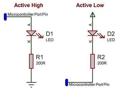
An active high LED will light when the microcontroller pin is outputting a logic 1 and be off when the microcontroller pin is outputting a logic 0 or in input mode.
An active low LED will light when the microcontroller pin is outputting a logic 0 and be off when the microcontroller pin is outputting a logic 1 or in input mode.
The series resistor can be on either side of the LED and acts to protect the LED from damage due to excess current. The value of resistor used can be changed based on the brightness of the LED and power consumption.
This LED Calculator tool is a good resource for calculating the correct LED series protection resistor.
LED Resistor Calculator Tool
Macro reference
Property reference

|
Properties
|

|
Connections
|

|
Pin
|
| Chip pin to connect the LED to.
|

|
Polarity
|
| Active High: Pin true -> On color, Pin false -> Off color Active Low: Pin true -> Off color, Pin false -> On color
|
|
|
Simulation
|

|
On Color
|
| The color of the indicator when it is turned on.
|
|
|
Off Color
|
| The color of the indicator when it is turned off.
|
|
|
Bezel Color
|
| Color of the bezel.
|
|
|
Label Color
|
| Color of the label text.
|

|
Text
|
| Text to show as the component label.
|

|
Font
|
| Font for the label text.
|
