Exercise - Create an LED Component: Difference between revisions
JohnVerrill (talk | contribs) |
JohnVerrill (talk | contribs) |
||
| Line 41: | Line 41: | ||
::* Select an appropriate pin, such as RA0, from the chip pin layout. | ::* Select an appropriate pin, such as RA0, from the chip pin layout. | ||
== | ==Reacting when a pin changes state== | ||
[[File:Gen_Exercise_LEDcreate_Proj_explorer.png|200px|right]] | |||
First, create a pin change macro. | |||
The [[Event Components.Property|Property change event]] is triggered when any property you have added to your component changes. | The [[Event Components.Property|Property change event]] is triggered when any property you have added to your component changes. | ||
* Open the [[Project Explorer]] from the [[View]] menu. | * Open the [[Project Explorer]] from the [[View]] menu. | ||
| Line 57: | Line 58: | ||
* Click on 'OK'. | * Click on 'OK'. | ||
Next, set up the 'PinChange' macro. | |||
* Select 'Show as Flowchart' from the 'Macro' menu, and choose the 'PinChange' macro. | |||
Add the following details: | |||
* Add a Decision icon to the PinChange | |||
==Updating when a pin changes== | ==Updating when a pin changes== | ||
Revision as of 16:39, 21 May 2013

Creating a graphic
- Open a new Flowcode flowchart.
- Make sure that the System Panel and Properties Panel are visible.
- If they are not, then select them in the View Menu.
- Click on the hemisphere shape in the Shapes menu and drag one onto the Systems Panel.
- The blue dotted square around it shows that this object is currently selected.
- Change the name of the component to 'LEDcomponent'.
- To do this:
- Find the 'handle' of the component at the top of the Panel Properties.
- Click on the name 'shape' (the default name).
- Change it to 'LEDcomponent'.
Adding properties
- Next, add two properties to the LED. The first allocates a color. The second sets up a connection from the LED to the controlling microcontroller.
- First add a default color to the component, using a new property called 'color'.
- To do this:
- De-select the hemisphere by clicking anywhere outside it in the Systems Panel.
- Hover over the icon to the right of the 'Properties' label.
- Click on the down-arrow that appears.
- Click on 'Add new'.
- In the 'Cosmetic name' box type "LEDcolor".
- Select 'Color picker' for the 'Property type'.
- Type "color" for the 'Property variable' name.
- In the same way, then add another new property to specify the default connection. Give it a Cosmetic name "Connection", with Property type 'Single digital pin' and a Property variable name "pin".
- Finally, configure these properties. To do this:
- Click on the color shown for the 'color' property.
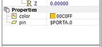
- Select a color from the color chart that appears.
- Click on the word 'Unconnected', alongside the 'pin' property.
- Select an appropriate pin, such as RA0, from the chip pin layout.
- Click on the color shown for the 'color' property.


Reacting when a pin changes state

First, create a pin change macro. The Property change event is triggered when any property you have added to your component changes.
- Open the Project Explorer from the View menu.
- Double-click on the item 'Connection -> PinChange'. The 'Add event' dialogue box opens.
- Hover over the icon to the left of the 'Macro' label. A drop-down arrow appears.
- Click on the arrow and select the option 'Add new'. The 'Edit Macro Details' dialogue box opens.
- Change the name of the macro to 'PinChange'.
- Click on 'OK'.
Next, set up the 'PinChange' macro.
- Select 'Show as Flowchart' from the 'Macro' menu, and choose the 'PinChange' macro.
Add the following details:
- Add a Decision icon to the PinChange
Updating when a pin changes
Because your component is connected to a pin, you want to run a flowchart when that pin changes. To do this, you can use the PinChange event.
To complete